


151
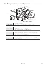
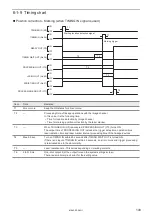
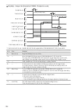
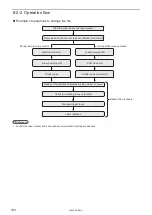
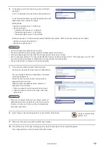
Position correction - Marking - Image checking (when TIMING IN signal is used)
ON
OFF
ON
OFF
ON
OFF
ON
OFF
ON
OFF
ON
OFF
ON
OFF
ON
OFF
ON
OFF
T1
T1
T1
T2
T4
T6
T4
T7
T8
T8
T3
T5
*1
TRIGGER IN (X5)
PROCESSING OUT (Y10)
CHECK OK OUT (No.34)
CHECK NG OUT (No.35)
PROCESSING END OUT (Y11)
SCRIPTING OUT (No.37)
TIMING IN (No.24)
TIMING WAIT OUT (No.36)
READY OUT (Y5)
Starting location
detection signal
Starting marking signal
Starting image checking signal
or
LASING OUT (No.40)
*1: CHECK OK OUT (No.34) / CHECK NG OUT (No.35) outputs is output before PROCESSING OUT (Y10) is turned OFF.
Item
Time
Remarks
T1
2ms or more
Keep the ON status for 2ms or more.
T2
―
Processing time of linkage operations with the image checker.
In this case, it is the following time.
• Time for location detection by image checker
• Time for marking position correction by the laser marker
T3
―
When TRIGGER IN (X5) is accepted, PROCESSING OUT (Y10) turns ON.
The output time of PROCESSING OUT includes the trigger delay time, operation time,
laser radiation time and laser marker internal processing time of the linkage devices.
T4
Max. 60 sec.
Turn on TIMING IN within 60 seconds after TIMING WAIT OUT is turned ON.
If there is no input of TIMING IN within 60 seconds, an error occurs and trigger processing
is terminated due to the abnormality.
T5
―
Laser radiation time. The time varies depending on marking contents.
T6
―
Processing time of communication and linkage operations with the image checker.
For code checking or character checking, time for transferring the marking data to the
image checker by the laser marker is included.
T7
―
Processing time of linkage operations with the image checker.
In this case, it is the following time.
• Time for reading by the image checker
• Time for transferring the checkup results from the image checker to the laser marker
T8
2 to 510 ms
One-shot output. Set the output time on the system settings screen.
There is a small margin of error for the setting value.
ME-LPRF-SM-11
Summary of Contents for LP-RF Series
Page 17: ...1 Product Overview ME LPRF SM 11...
Page 34: ...2 Laser Marker Installation ME LPRF SM 11...
Page 57: ...3 Operation Method ME LPRF SM 11...
Page 81: ...4 External Control Using I O ME LPRF SM 11...
Page 126: ...5 External Control by Communication Commands ME LPRF SM 11...
Page 135: ...6 Link Control with External Devices ME LPRF SM 11...
Page 160: ...7 Maintenance ME LPRF SM 11...
Page 186: ...Troubleshooting ME LPRF SM 11...
Page 214: ...Index ME LPRF SM 11...
Page 216: ...216 USB 32 55 W Warning 205 ME LPRF SM 11...
Page 217: ......


