


95
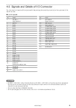
No.
Name and description
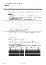
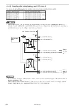
19 to 21
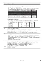
SELECT 0 IN to SELECT 2 IN
With SELECT 0 IN to SELECT 2 IN, the setting target of D0 IN to D15 IN and Guide laser indication target
are specified.
• Select the setting target of D0 IN to D15 IN
Specify SELECT 0 IN to SELECT 2 IN corresponding to the setting target shown below. Keeping the input
of SELECT 0 IN to SELECT 2 IN and D0 IN to D15 IN (No.3 to 18), turn ON SET IN (No.2).
Setting target of D0 IN to D15 IN
SELECT 0 IN
SELECT 1 IN
SELECT 2 IN
File No.
OFF
OFF
OFF
Count up value correction
OFF
ON
OFF
Count down value correction
ON
ON
OFF
Counter number to reset
OFF
OFF
ON
Data number of registered characters/
external offset
ON
OFF
OFF
• Select guide laser indication target
Specify SELECT 0 IN to SELECT 2 IN corresponding to the indication target of guide laser as shown
below. Keeping the input of SELECT 0 IN to SELECT 2 IN, turn ON GUIDE IN (No.23).
Indication by guide laser
SELECT 0 IN
SELECT 1 IN
SELECT 2 IN
Work distance
OFF
OFF
OFF
Marking image
ON
OFF
OFF
Marking field
OFF
ON
OFF
Masked objects
ON
ON
OFF
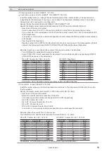
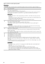
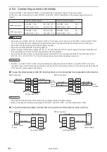
22
TIME HOLD IN: Time/date hold input
Performs marking of date and lot, reflecting the time when the input is turned ON.
While this input is turned on, the laser marker retains the time and date of the system clock at the point when
the input was turned ON, then it marks the functional characters for current date, expiry date, and lot.
TIME HOLD IN is available even when the remote mode is turned off.
If TIME HOLD IN is turned ON when powering on the laser marker, it retains the system startup time.
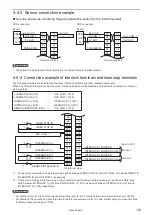
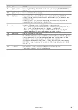
23
GUIDE IN: Guide laser radiation input
The guide laser irradiates while the input is turned ON. (Up to one minute)
Determine the guide laser radiation details by the combination of SELECT 0 IN to SELECT 2 IN (No.19 to
No.21). Keep the input state of SELECT 0 IN to SELECT 2 IN while GUIDE IN is turned ON.
This terminal is available when the guide laser control method is set to I/O at the system settings of Laser
Marker NAVI smart.
Input this terminal with the shutter closed.
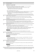
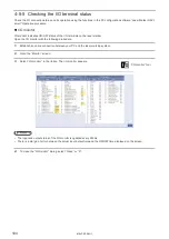
24
TIMING IN
This is the terminal you will use when the link control function with the image checker is configured.
Turn this terminal ON when you instruct the operation timing to the laser marker or to the target device
controlled by the link function. Starts the link control processing by edge of input ON.
Input this terminal within 60 seconds from turning ON of TIMING WAIT OUT (No.36).
For details, refer to “6-1 Link Control with Image Checker” (P.136).
25, 26
RESERVE: System reservation
Do not connect externally.
ME-LPRF-SM-11
Summary of Contents for LP-RF Series
Page 17: ...1 Product Overview ME LPRF SM 11...
Page 34: ...2 Laser Marker Installation ME LPRF SM 11...
Page 57: ...3 Operation Method ME LPRF SM 11...
Page 81: ...4 External Control Using I O ME LPRF SM 11...
Page 126: ...5 External Control by Communication Commands ME LPRF SM 11...
Page 135: ...6 Link Control with External Devices ME LPRF SM 11...
Page 160: ...7 Maintenance ME LPRF SM 11...
Page 186: ...Troubleshooting ME LPRF SM 11...
Page 214: ...Index ME LPRF SM 11...
Page 216: ...216 USB 32 55 W Warning 205 ME LPRF SM 11...
Page 217: ......


