


140
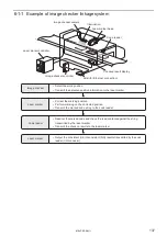
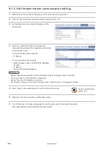
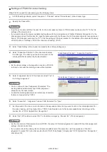
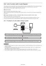
6-1-4 Set the laser marker communication settings
1.
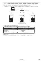
Establish an online connection between your PC and the laser marking system.
2.
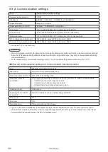
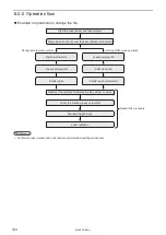
Go to the “System settings” screen and select “Communication” tab.
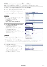
3.
Set the Ethernet communication configuration of the
laser marker.
4.
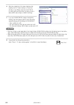
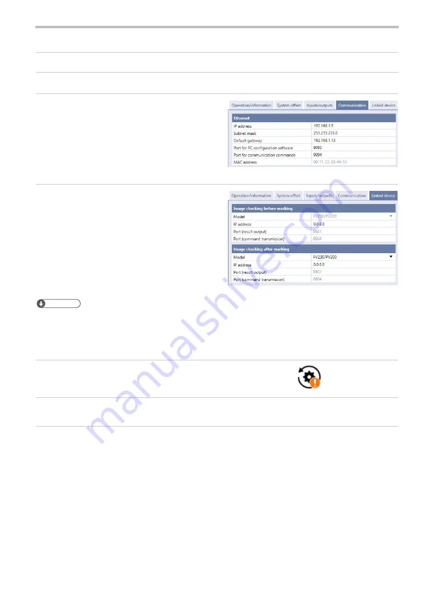
Open the “Linked device” tab and configure the
communication settings of the imagechecker according
to the functions to use.
For image checking before marking:
• IP Address
For image checking after marking:
• Model of image checker: PV230/PV200, DataMan,
LP-ABR
• IP Address
• Port (for LP-ABR and DataMan)
ンㄆㄇㄆㄓㄆㄏㄆ
• Specify these values according to communication settings of the image checker to connect.
• The Port number for PV230/PV200 is a fixed value.
• Specify Telnet Port for DataMan port number.
• For LP-ABR, set the port number with the same value of “Data Port No” in Configurator LP-ABR.
5.
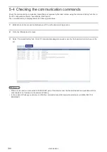
Select “Apply to laser marking system” on the left side of the ribbon.
6.
Disconnect the online connection with the laser marker.
7.
Turn off the power of the laser marking system, wait five seconds and then restart the system.
The configured items will be reflected to the laser marker.
“Apply to laser marking
system” tool
ME-LPRF-SM-11
Summary of Contents for LP-RF Series
Page 17: ...1 Product Overview ME LPRF SM 11...
Page 34: ...2 Laser Marker Installation ME LPRF SM 11...
Page 57: ...3 Operation Method ME LPRF SM 11...
Page 81: ...4 External Control Using I O ME LPRF SM 11...
Page 126: ...5 External Control by Communication Commands ME LPRF SM 11...
Page 135: ...6 Link Control with External Devices ME LPRF SM 11...
Page 160: ...7 Maintenance ME LPRF SM 11...
Page 186: ...Troubleshooting ME LPRF SM 11...
Page 214: ...Index ME LPRF SM 11...
Page 216: ...216 USB 32 55 W Warning 205 ME LPRF SM 11...
Page 217: ......


