GTWIN Reference Manual
2.7 FP Monitor
89
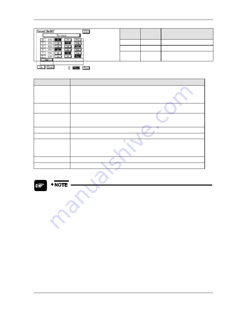
Device
type
Device
No.
Device value
C
256
Forced ON
T
256
Forced OFF
L
100
Not forced, i.e. free to be
controlled by the PLC.
Option
Description
Release
Deletes the list and releases all forced bit devices. However, if the PLC is in the
PROG. mode or the device was forcibly turned ON without the state being changed in
the PLC program, the bit device may not turn OFF correctly. We recommend turning
OFF the bit device forcibly before selecting [Release].
Device type
Displays the currently selected device type. Touch the button to change the device
type.
Device No.
Displays the number of the device (address). To enter a number, touch the number
field and wait for the keyboard to display. Alternatively, use the [Up]/[Down] buttons to
select a device.
ON
Forces the bit device ON.
OFF
Forces the bit device OFF.
Free
Specifies that the bit device should operate as specified by the PLC program.
However, if the PLC is in the PROG. mode or the device was forcibly turned ON or
OFF without the state being changed in the PLC program, the bit device will remain in
the forced state.
Add
Select this button to add another bit device.
[Up]/[Down]
Use the buttons to scroll through the list of devices.
When using the FP monitor, do not force bit devices ON/OFF with another
tool such as
FPWIN Pro / FPWIN GR
. Otherwise, the display on the "Forced
On/Off" screen of the FP Monitor may differ from the status of the PLC.
All forced inputs/outputs in the PLC will be released when you switch the
PLC from RUN to PROG. or PROG. to RUN.
In the PROG. mode, you can only turn ON the following bit devices: Y
(external output), R (internal relay), and L (link relay).
To save the bit devices in the list, press [Esc] to return to the device
monitor.
Summary of Contents for GTWIN
Page 1: ...TOUCH TERMINALS GTWIN Reference Manual ...
Page 11: ...Chapter 1 Introducing GTWIN ...
Page 59: ...Chapter 2 GT Panel System Menu ...
Page 94: ...Chapter 3 The GTWIN User Interface ...
Page 108: ...Chapter 4 Menus ...
Page 182: ...Chapter 5 Parts and Their Functions ...
Page 234: ...Chapter 6 Troubleshooting ...
Page 248: ...Chapter 7 Connecting the GT to a PLC ...
Page 288: ...Chapter 8 SD Card Data Upload from GT to PC ...
Page 293: ......


