GTWIN Reference Manual
5.9 Line Graph Parts
209
Tab
Field
Description
display the
setting
options)
Reverse/Blink
You can specify how the part appears, e.g. if it blinks, etc., under normal
conditions or when a certain condition is true.
Press [Setup] to choose from among an extensive range of conditions.
The setting for "When Condition is True" takes priority over the setting for
"Normal".
Color and Form
Line Type/Color/Mark
. Specify the thickness and the color of the line as
well as a distinguishing mark, if necessary.
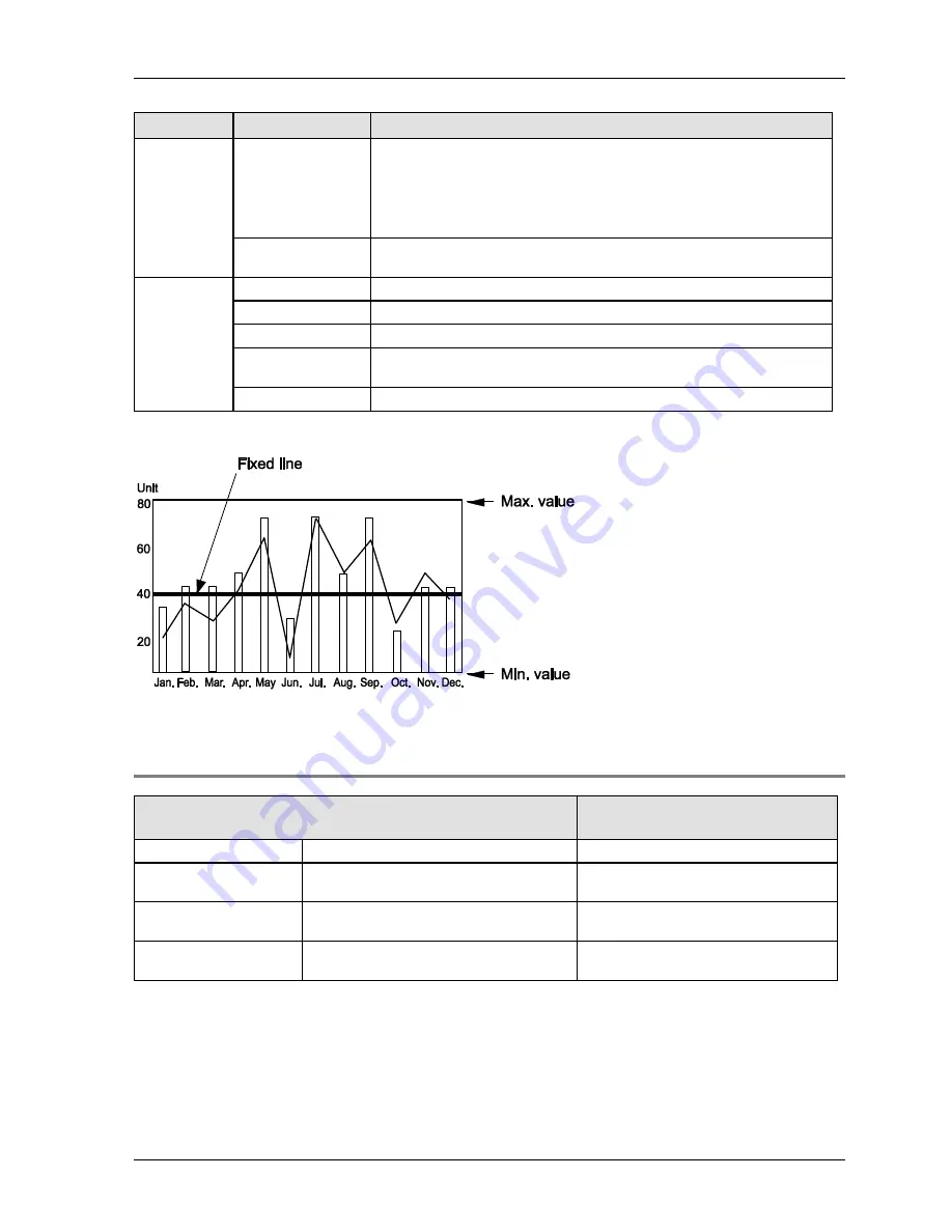
Display Fixed
Line
(select
[Setup] to
display the
setting
options)
Comment
Add a comment here if desired.
Data Format
Select the same data format as the one specified under "Line Settings".
Max./Min.
Set the maximum/minimum value for the fixed line.
Value (Position)
Set the position of the fixed line in the graph. The value has to be within
the range specified by "Max./Min.".
Line Type/Color
Specify the thickness and the color of the line.
Display fixed line in a line graph part
5.9.1.1 "Display Data" Options on "Display" Tab
When "Bar Graph" = "Yes" on the "Basic Setup" tab
When "Bar Graph" = "No" on the
"Basic Setup" tab
Bar Width
Specify width of the bars (see below).
Margin between Bars
Specify the distance between the
individual bars.
Margin from Edge
Specify the distance from the line graph
frame
Plot Interval
Read-only field. Value is set automatically
by the system
Specify the distance between each plot
displayed in the line graph.
Summary of Contents for GTWIN
Page 1: ...TOUCH TERMINALS GTWIN Reference Manual ...
Page 11: ...Chapter 1 Introducing GTWIN ...
Page 59: ...Chapter 2 GT Panel System Menu ...
Page 94: ...Chapter 3 The GTWIN User Interface ...
Page 108: ...Chapter 4 Menus ...
Page 182: ...Chapter 5 Parts and Their Functions ...
Page 234: ...Chapter 6 Troubleshooting ...
Page 248: ...Chapter 7 Connecting the GT to a PLC ...
Page 288: ...Chapter 8 SD Card Data Upload from GT to PC ...
Page 293: ......


