Solution System
96
Service Manual – SC1500
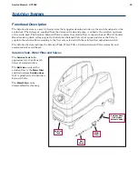
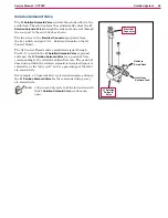
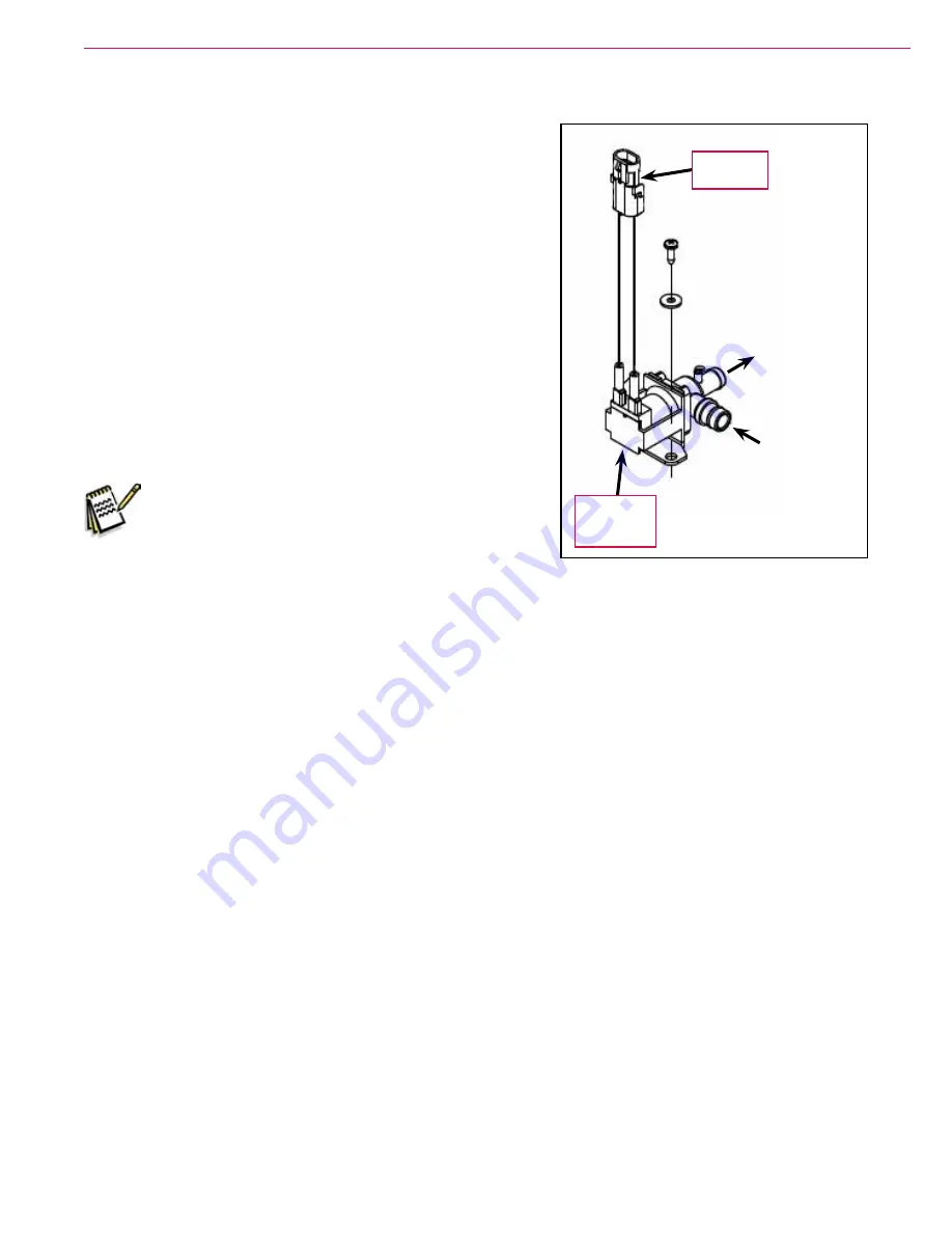
Solution Solenoid Valve
The
L1 Solution Solenoid Valve
controls the solution flow to the
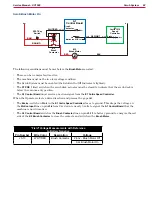
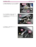
scrub deck. The solution from the solution tank enters the
L1
Solution Solenoid Valve
through the side port and exits through
the rear port to the scrub deck as shown.
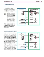
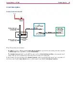
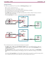
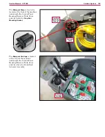
The two wires in the
Electrical Connector
get power from
the key switch and pin J3-11 - Solution Solenoid on the A1
Control Board.
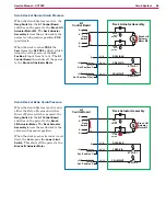
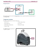
The A1 Control Board sends a modulated signal through
Pin J3-11 to switch the
L1 Solution Solenoid Valve
to ground
and open the
L1 Solution Solenoid Valve
for a period of time
corresponding to the selected solution flow rate. The period of
time during which the solution solenoid is energized (open) is
referred to as the “duty cycle” and is a percentage of the total
six-second cycle.
For example, a 50-percent duty cycle would energize and open
the
L1 Solution Solenoid Valve
for three seconds during every
six-second cycle.
Note:
100 percent duty cycle is full solution flow with
the
L1 Solution Solenoid Valve
continuously
open.
Electrical
Connector
Inlet from
Solution Tank
Outlet to
Scrub Deck
L1 Solution
Solenoid
Valve

