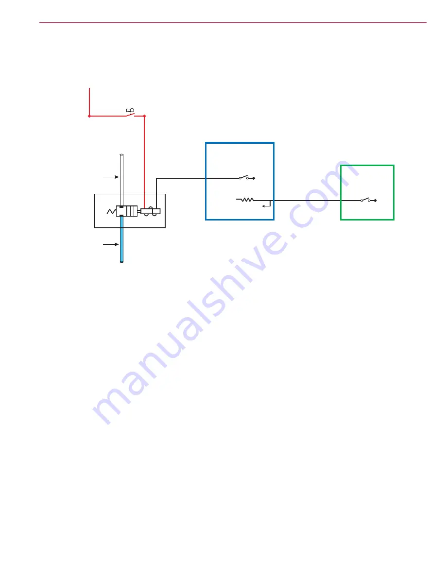
Solution System
98
Service Manual – SC1500
Circuit Descriptions
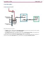
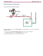
Solution Solenoid Valve Off
S1
2
1
Bat +
Bat -
Bat -
Pin 6
J3-6
+24v
J3-11
BRN/VIO
RED/WHT
VIO/BLK
A1
Control Board
L1 Solution
Solenoid Valve
(closed)
Solution Line from
Solution Tank
Solution Line from
Solenoid Valve
to Scrub Deck
SPST Key
Switch
Solution
Solenoid
Motion Input 24v
Brake -
E1 Curtis
1210 Speed
Controller
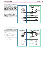
When the machine is stationary:
• The
Brake -
switch on
Pin 6
in the
E1 Curtis Speed Controller
is open and is not sending the drive signal to
the
Motion Input
line on pin
J3-6
on the
A1 Control Board
• The
Solution Solenoid
switch on pin
J3-11
is open, and the
L1 Solution Solenoid Valve
is de-energized and
closed. This prevents solution flow from the solution tank to the scrub deck.
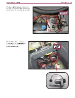
If the Solution System is disabled, the
Solution Solenoid
switch on pin
J3-11
will remain open regardless of
whether or not the
A1 Control Board
receives a drive signal from the
E1 Curtis Speed Controller

