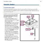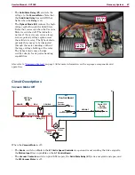
Recovery System
68
Service Manual – SC1500
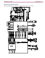
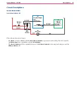
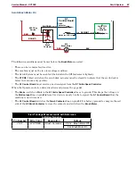
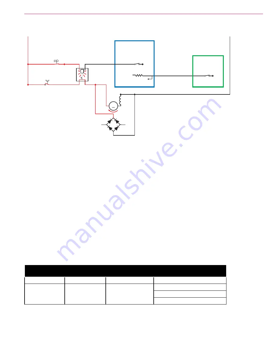
Vacuum Motor On
S1
2
1
Bat -
Pin 6
J3-6
24v
Bat -
J3-12
Bat +
Bat -
Brake -
2
1
1-
2+
CB3
4-
3+
1
2
M4
D2
M
+
~
~
-
BRN/VIO
BLU/ORN
WHT
GRA/BLK
BRN
RED/WHT
SPST Key
Switch
Vacuum
Contactor
Solid State
Relay (K1)
A1
Control Board
E1
Curtis 1210
Speed
Controller
Motion Input (0.1v)
Circuit Breaker, 20 Amp
Vacuum
Motor
Fly-back
Diode
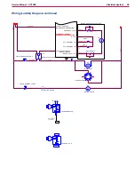
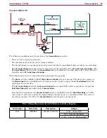
The following conditions must be met before the
Vacuum Motor
can start:
• There can be no major faults active.
• The machine must not be in a low-voltage condition.
• The Scrub System or vacuum mode must be activated (the Vacuum Mode Indicator will be on or flashing).
• The
A1 Control Board
must have recently detected a motion signal from the
E1 Curtis Speed Controller
. (The
A1 Control Board
will switch off the
Vacuum Motor
after a maximum 10 second delay once it loses the drive
signal from the
E1 Curtis Speed Controller
)
When the Operator selects a drive direction and presses the go pedal:
• The
Brake -
switch on
Pin 6
in the
E1 Curtis Speed Controller
closes to ground. This drops the voltage on
the
Motion Input
line on pin
J3-6
from 24v down to nearly 0 volts to signal the
A1 Control Board
that the
machine is now in motion.
• The
A1 Control Board
switches the
Vacuum Contactor
line on pin
J3-12
to battery ground to energize the
Solid State Relay (K1)
and switch on the
Vacuum Motor
Note that the output from the
Vacuum Contactor
line on pin
J3-12
drives the
Solid State Relay
at 100 Hz
with either a 100% duty cycle for the high/standard vacuum mode, or a modulated (60%) duty cycle to
provide an average of 16.8V to the
Vacuum Motor
in the low/quiet vacuum mode.
“Field” Voltage Measurements with Reference to Battery Negative
Pin Number
Wire Color
Description
Voltage
J3-12
GRA/BLK
Vacuum Contactor
23.4v - Vacuum Off
6.9v - Vacuum Low/Quiet
0.104v - Vacuum High/Standard

