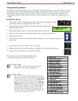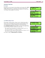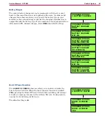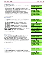
Control System
29
Service Manual – SC1500
Service Test Mode Functions
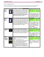
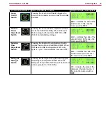
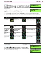
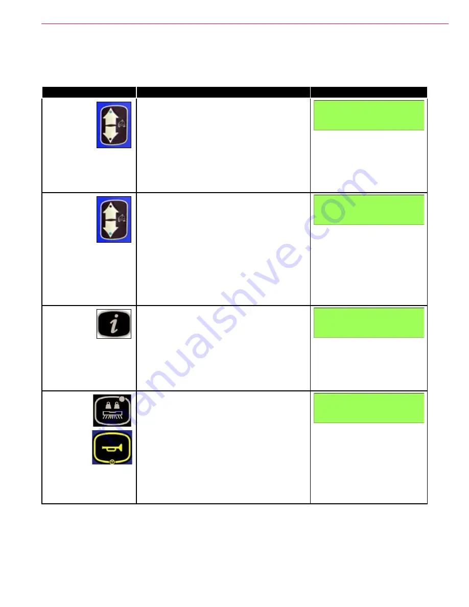
The control panel switches are used to control various A1 Control Board output functions. The table below
lists the control panel switches, and their corresponding Service Test Mode functions and displays:
Control Panel Switch
Service Test Mode Function
Graphic Display Descriptions
Forward
Drive
Switch
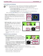
The Forward Drive Switch enables the machine
to drive forward. The blue LED indicator will be
lit when the Switch is active. For the machine
to move forward, the Emergency Stop must be
reset, the Operator Presence Pedal must be
pressed and the Go Pedal must be pressed.
Note that the Inhibit (
INH
) output must be off (via
the Information Switch – see below).
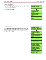
•
SPD:
– indicates the drive
controller state. In this case it
would display
F
for forward.
•
The three digits display the
battery voltage (
26.5
volts in
this example).
Reverse
Drive
Switch
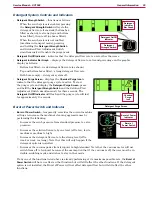
The Reverse Drive Switch enables the machine
to drive in reverse. The blue LED indicator will
be lit when the Switch is active. For the machine
to move backward, the Emergency Stop must
be reset, the Operator Presence Pedal must be
pressed and the Go Pedal must be pressed.
Note that the Inhibit (
INH
) output must be off (via
the Information Switch – see below).
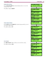
•
SPD:
– indicates the drive
controller state. In this case it
would display
R
for reverse.
•
The three digits display the
battery voltage (
26.5
volts in
this example).
•
REV:
– indicates that the
reverse output is
ON
.
Information
Switch
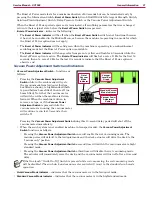
Pressing the Information Switch toggles the
Inhibit output (
INH
) from the A1 Control Board to
the E1 Curtis Speed Controller
ON
and
OFF
. Note
that
INH
must be
OFF
in order to test the forward
and reverse drive in the Service Test Mode.
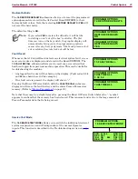
•
INH:
– indicates the state of
the inhibit signal. In this case
the inhibit signal is
ON
.
•
E(NN)
– displays any active
fault codes.
Extra
Pressure
and Horn
Switches
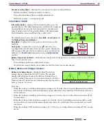
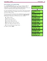
Pressing the Extra Pressure Switch scrolls
the
DEK:
field through the four available deck
positions:
•
UP
– raised (transport) position
•
VAC
– vacuum-only (wet vacuuming) position
•
LOW
– standard scrub pressure position
•
HI
– extra scrub pressure position
Pressing the Horn Switch will move the deck
to the selected position. Note that the Extra
Pressure Switch is locked out while the deck is
moving. The
DEK:
line will be highlighted and
inverted.
DEK:
– indicates the scrub deck
position. In this case the deck
would be in the
UP
(transport)
position.
SPD: F 26.5
BRU: OFF
REV: OFF
VAC: OFF
INH: ON E00
SOL: OFF
DEK: UP
CP: OFF
SPD: R 26.5
BRU: OFF
REV: ON
VAC: OFF
INH: ON E00
SOL: OFF
DEK: UP
CP: OFF
SPD: R 26.5
BRU: OFF
REV: ON
VAC: OFF
INH: ON E00
SOL: OFF
DEK: UP
CP: OFF
SPD: R 26.5
BRU: OFF
REV: ON
VAC: OFF
INH: ON E00
SOL: OFF
DEK: UP
CP: OFF

