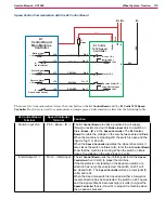
Solution System
100
Service Manual – SC1500
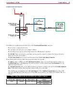
Detergent Pump On
The following conditions must be met before the
M2 Detergent Pump
can start:
• There can be no major faults active.
• The machine must not be in a low-voltage condition.
• The Scrub System must be enabled (the Solution On/Off Indicator is lighted).
• The Detergent System must be installed and enabled.
• The
S7 POS 1
limit switch on the scrub deck actuator must be closed to indicate that the scrub deck is
below the vacuum-only position.
• The
A1 Control Board
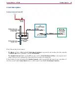
must receive a motion signal from the
E1 Curtis Speed Controller
Bat -
Pin 6
J3-6
24v
Pin 6
M2
-
+
M
J1-3 -
J1-1 +
Bat +
Bat -
Bat +
RED/YEL
BLU/GRA
RED/WHT
Detergent
Pump
Detergent
Pump
Detergent
Pump
Brake -
A1
Control Board
E1
Curtis 1210
Speed
Controller
Motion Input (0.1v)
Bat -
Pin 6
J3-6
24v
Pin 6
M2
-
+
M
J1-3 -
J1-1 +
Bat +
Bat -
Bat +
RED/YEL
BLU/GRA
RED/WHT
Detergent
Pump
Detergent
Pump
Detergent
Pump
Brake -
A1
Control Board
E1
Curtis 1210
Speed
Controller
Motion Input (0.1v)
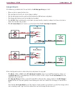
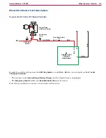
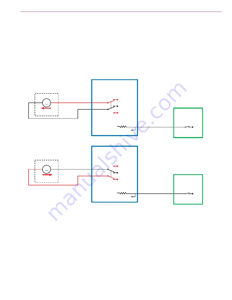
When the Operator selects a drive direction and presses the go pedal:
• The
Brake-
switch on
Pin 6
in the
E1 Curtis Speed Controller
closes to ground. This drops the voltage on
the
Motion Input
line on pin
J3-6
from 24v down to nearly 0 volts to signal the
A1 Control Board
that the
machine is now in motion.
• The
Detergent Pump
switches on pins
J1-1
and
J1-3
to alternate the voltage polarity to the
M2 Detergent
Pump
. This moves the pump plunger and diaphragm in and out to deliver the detergent to the solution
line.
Note that the
A1 Control Board
varies the number of pump strokes per minute to control the detergent flow
rate according to deck type, and the solution flow rate and detergent ratio selected.

