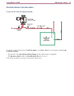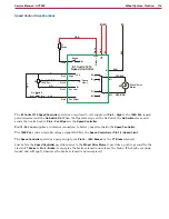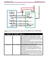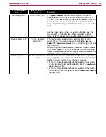
Wheel System - Traction
123
Service Manual – SC1500
Removal and Installation
Drive Wheel Assembly
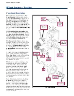
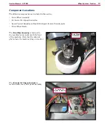
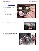
1
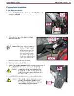
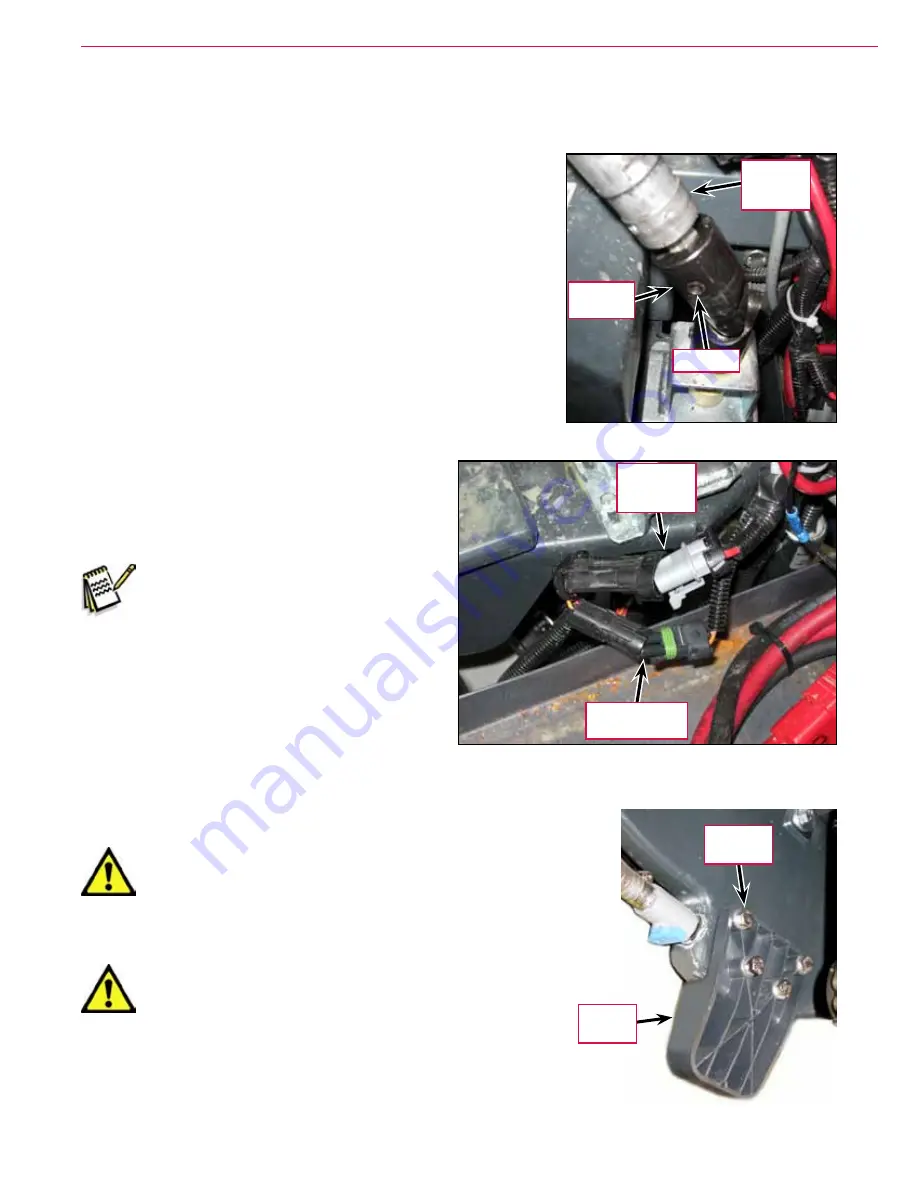
Loosen the
Setscrew
holding the
Steering Assembly Tube
in the
lower
Universal Joint
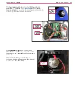
2
Disconnect the upper
Drive Motor
and
Brake
Electrical Connectors
Service Tip:
You may find it easiest to
lay the machine down on
a raised, padded surface
when removing the drive
wheel assembly. In this
case you’ll need to drain
the solution and recovery
tanks, remove the batteries
and remove the tip pads.
3
Drain the solution and recovery tanks.
4
Disconnect and remove the batteries.
5
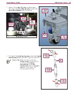
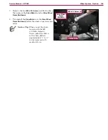
Remove the four
M8 x 30 Screws
and flat washers holding each of
the two
Tip Pads
to the machine and remove the
Tip Pads
Caution: Tipping the machine on its side without first
removing the Tip Pads can damage the Tip
Pads and strip the molded-in fasteners out of
the solution tank.
6
Carefully lay the machine down on a clean, padded surface.
Caution: The machine is heavy. Make sure you have
the adequate manpower available to lay
the machine on its side without causing any
personal injury or machine damage.
Steering
Assembly
Tube
Universal
Joint
Setscrew
Drive Motor
Electrical
Connector
Brake Electrical
Connector
Tip Pad
(typical)
M8 x 30
Screw (4)

