Electrical System
48
Service Manual – SC1500
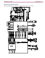
Interlock Circuit
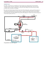
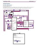
The battery charger has an “interlock circuit” which consists of an internal relay that interrupts the
“Deadman” signal to the main control board, and the Keyswitch Input (KSI) signal to the drive speed
controller when the charger is plugged into an AC power outlet. This prevents the machine from being
propelled while the batteries are charging.
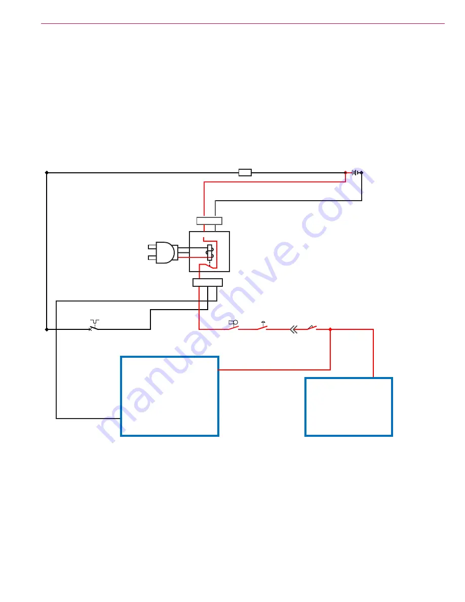
Here is how the battery charger interlock circuit works. The interlock relay contacts inside the charger are
normally closed, allowing positive control voltage to be present in the Keyswitch, E-Stop, and Deadman
circuit. When all switches are closed, positive voltage is applied to the enabling inputs of the A1 Control
Board and the Speed Controller. When the AC power cord is plugged in, the relay is energized and opens the
relay contacts opening the circuit.
BT1
Battery 24 VDC
+
-
RED
BLK
Emergency
Stop
S4
S1
S2
Dead Man Switch
K
L
B
O
I
V
/
N
R
B
D
E
R
Circuit Breaker, 5 Amp
SPST Key
Switch
2
2
2
2
1
1
1
1
J2-3 Bat Charger
On-board Communication
CB2
YEL/ORN
YEL/ORN
Gnd
1 2 3
A
B
B+ B-
RED
F1
Fuse, 150 A.
1
2
A1
Control Board
Main Machine
Controller
E1
Curtis 1210
Speed
Controller
Pin 5 - KSI
BRN
Dead Man
Switch J3-4
Internal Relay
in Battery Charger
Not Used
Not Used
Charger Interlock Circuit, Not Plugged In

