Recovery System
72
Service Manual – SC1500
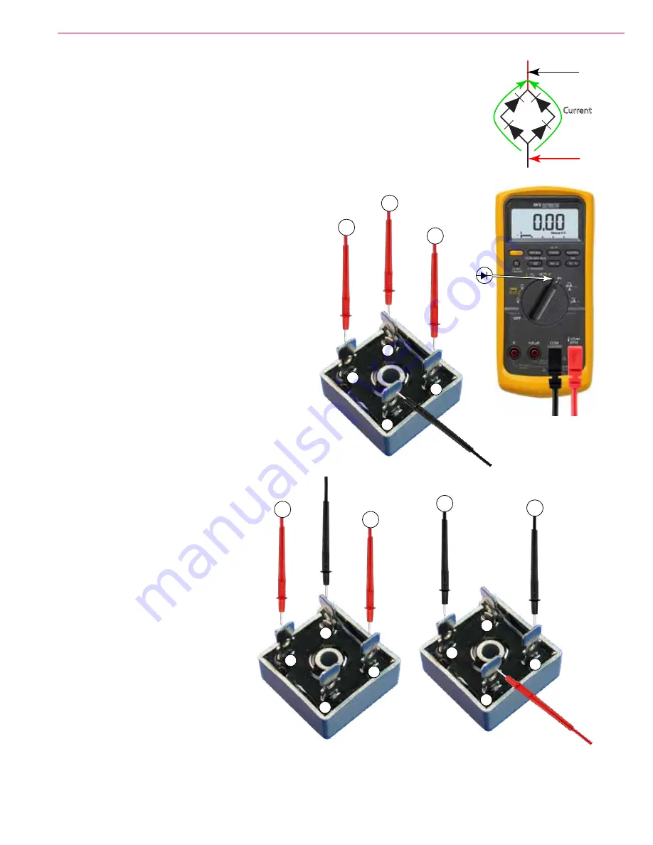
Bench-testing the Fly-back Diode (bridge rectifier)
When functioning properly, the flyback diode should conduct only when the voltage gets
reversed by the vacuum motor. To test the bridge rectifier, use a DC continuity tester or
an ohm meter (on the R x 100 scale) as follows. If any of the internal diodes are shown
to be defective in any of the following steps the rectifier must be replaced. (Refer to
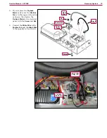
steps 8 and 9 for the correct mounting position and wire connections.)
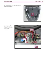
Note that the positive tab on the Flyback Diode is rotated 90 degrees from the other
three tabs.
1
Disconnect the two wires from the Flyback
Diode.
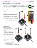
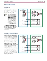
Reverse Bias Test
In the reverse bias direction, none of the internal
diodes should conduct.
2
Connect the negative test lead to the negative
terminal on the rectifier.
3
One at a time, touch the positive test lead to the
remaining 3 terminals.
• If the meter beeps or reads continuity for any
of the 3, then the rectifier is defective.
• If the meter does not beep, continue with the
next step.
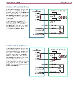
Forward Bias Test
In the forward bias direction, all
of the diodes should conduct. Due
to parallel paths, the positive and
negative terminals have to be checked
separately.
4
Connect the negative test lead
to the positive terminal on the
rectifier.
5
One at a time, touch the positive
test lead to the 2 AC terminals
(1&2)
6
Connect the positive test lead to the
negative terminal on the rectifier.
7
One at a time, touch the negative
test leads to the 2 AC terminals
(3&4)
• If the meter does not beep or
reads open circuit for any of the 4,
then the rectifier is defective.
• If the meter beeps for all 4, then the rectifier is good.
+
~
~
-
Positive
Negative
Current
+
~
–
~
1
2
3
+
~
–
~
1
2
+
~
–
~
3
4

