ENGINE MAIN PARTS - INSPECTION AND CORRECTION
2 - 23
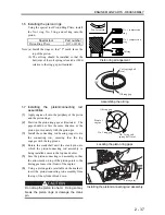
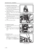
2. Flywheel, Timing Gear, Camshaft
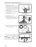
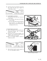
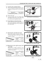
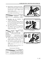
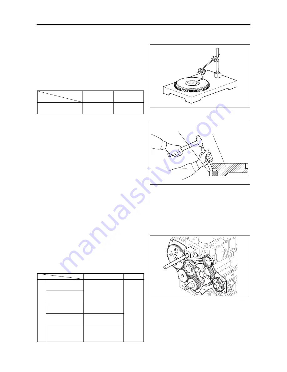
2.1 Measuring the flywheel flatness
Place the flywheel on a surface plate. Run a dial
gauge over the frictional surface of the flywheel
to measure the flatness.
If the measured value exceeds the limit, grind the
frictional surface.
Unit: mm (in.)
Standard
value
Limit
Flywheel flatness
0.150 (0.0059)
or less
0.50 (0.0197)
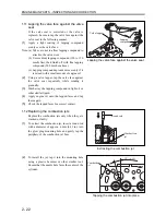
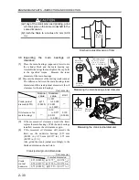
2.2 Replacing the ring gear
Check the ring gear for fractured or excessively
worn gear teeth. If faulty, replace in the
following manner.
(1)
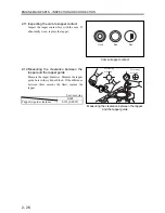
Removing the ring gear
(a) Using an acetylene torch or other similar
equipment, heat the ring gear evenly.
(b) Using a hammer and a rod, tap the ring gear
evenly on the entire periphery until the gear
comes off.
(2)
Installing the ring gear
Using a piston heater or other similar equipment,
heat the ring gear [to approximately 150
℃
(302
°
F
) or less]. With the gear warmed up, install it
onto the flywheel with the un-chamfered side
first.
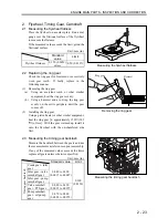
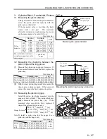
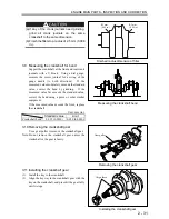
2.3 Measuring the timing gear backlash
Measure the backlash between the gears and use
the measurements as references upon reassembly.
If any of the measured values exceeds the limit,
replace all gears unless otherwise specified.
Unit: mm (in.)
Standard
value
Limit
Crank gear - idler
gear
Idler gear - valve
camshaft gear
Idler gear - pump
camshaft gear
0.040 to 0.120
(0.0015 to 0.0047)
Valve camshaft
gear - PTO gear
0.080 to 0.190
(0.0032 to 0.0075)
T
iming gear backlash Pump camshaft
gear - oil pump
gear
0.070 to 0.200
(0.0028 to 0.0079)
0.300
(0.0120)
Measuring the flywheel flatness
Removing the ring gear
Measuring the timing gear backlash
Flywheel
Ring gear
Summary of Contents for diesel engines
Page 5: ......
Page 33: ...SERVICE STANDARDS 1 20 ...
Page 34: ...1 General Tools 1 22 2 Special Tools 1 23 TOOLS LIST ...
Page 37: ...TOOLS LIST 1 24 ...
Page 41: ...OVERHAUL TIMING 1 28 ...
Page 46: ......
Page 47: ......
Page 61: ...ENGINE MAIN PARTS DISASSEMBLY 2 16 ...
Page 99: ...FUEL SYSTEM REMOVAL 3 8 ...
Page 115: ...FUEL SYSTEM DISASSEMBLY INSPECTION AND REASSEMBLY 3 24 ...
Page 119: ...FUEL SYSTEM INSTALLATION 3 28 2 Governor Installing the governor Installation sequence ...
Page 123: ...FUEL SYSTEM INSTALLATION 3 32 ...
Page 131: ...OIL SYSTEM DISASSEMBLY INSPECTION AND REASSEMBLY 4 8 ...
Page 143: ...COOLING SYSTEM DISASSEMBLY INSPECTION AND REASSEMBLY 5 8 ...
Page 150: ......
Page 151: ......
Page 153: ...INLET AND EXHAUST SYSTEMS REMOVAL 6 4 ...
Page 159: ...INLET AND EXHAUST SYSTEMS INSTALLATION 6 10 ...
Page 160: ...1 Starter 7 2 2 Alternator 7 3 3 Stop Solenoid 7 4 4 Glow Plug 7 5 ELECTRICAL SYSTEM REMOVAL ...
Page 165: ...ELECTRICAL SYSTEM REMOVAL 7 6 ...
Page 189: ...ELECTRICAL SYSTEM INSTALLATION 7 30 ...
Page 207: ...MISCELLANEOUS 9 4 ...

