


FUEL SYSTEM - INSTALLATION
3 - 29
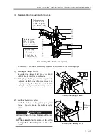
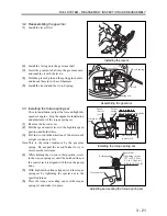
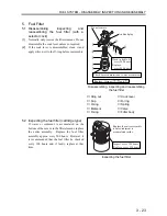
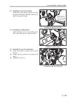
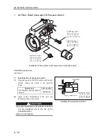
2.1 Installing the governor weights
Install the governor weights onto the rear end of
the pump camshaft and tighten the sliding sleeve
shaft to the specified torque.
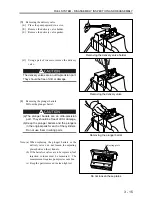
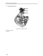
2.2 Installing the sliding sleeve
Install the sliding sleeve onto the sliding sleeve
shaft. Ensure that the sleeve slides smoothly.
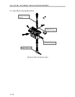
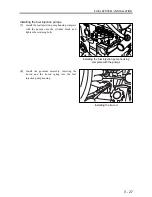
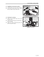
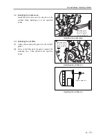
2.3 Installing the governor assembly
(1)
Install the governor assembly onto the pump
housing.
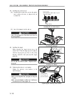
(2)
Connect the tie-rod and the tie-rod spring to the
pumps.
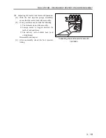
(3)
Install the tie-rod cover.
Installing the governor weights
Installing the sliding sleeve
Installing the governor assembly
Tightening torque:
29.4 to 41.2 N m
(3.0 to 4.2 kgf m)
[21.7 to 30.4 lbf ft]
Summary of Contents for diesel engines
Page 5: ......
Page 33: ...SERVICE STANDARDS 1 20 ...
Page 34: ...1 General Tools 1 22 2 Special Tools 1 23 TOOLS LIST ...
Page 37: ...TOOLS LIST 1 24 ...
Page 41: ...OVERHAUL TIMING 1 28 ...
Page 46: ......
Page 47: ......
Page 61: ...ENGINE MAIN PARTS DISASSEMBLY 2 16 ...
Page 99: ...FUEL SYSTEM REMOVAL 3 8 ...
Page 115: ...FUEL SYSTEM DISASSEMBLY INSPECTION AND REASSEMBLY 3 24 ...
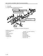
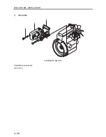
Page 119: ...FUEL SYSTEM INSTALLATION 3 28 2 Governor Installing the governor Installation sequence ...
Page 123: ...FUEL SYSTEM INSTALLATION 3 32 ...
Page 131: ...OIL SYSTEM DISASSEMBLY INSPECTION AND REASSEMBLY 4 8 ...
Page 143: ...COOLING SYSTEM DISASSEMBLY INSPECTION AND REASSEMBLY 5 8 ...
Page 150: ......
Page 151: ......
Page 153: ...INLET AND EXHAUST SYSTEMS REMOVAL 6 4 ...
Page 159: ...INLET AND EXHAUST SYSTEMS INSTALLATION 6 10 ...
Page 160: ...1 Starter 7 2 2 Alternator 7 3 3 Stop Solenoid 7 4 4 Glow Plug 7 5 ELECTRICAL SYSTEM REMOVAL ...
Page 165: ...ELECTRICAL SYSTEM REMOVAL 7 6 ...
Page 189: ...ELECTRICAL SYSTEM INSTALLATION 7 30 ...
Page 207: ...MISCELLANEOUS 9 4 ...