ENGINE MAIN PARTS - INSPECTION AND CORRECTION
2 - 22
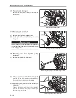
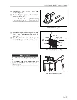
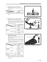
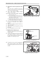
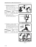
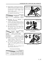
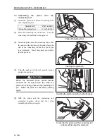
1.11 Lapping the valve face against the valve
seat
If the valve seat is corrected or the valve is
replaced, be sure to lap the valve face against the
valve seat in the following manner.
(1)
Apply a light coating of lapping compound
evenly over the valve face.
Note: (a) Take care not to allow lapping compound to
attach to the valve stem.
(b) Use medium lapping compound (120 to 150
mesh) first, then finish off with fine lapping
compound (200 mesh or above).
(c) Lapping compound spreads more evenly if it
is mixed with a small amount of engine oil.
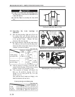
(2)
Using a valve lapper, lap the valve face against
the valve seat repeatedly while rotating it
gradually.
(3)
Wash away the lapping compound in light oil or
other similar liquid.
(4)
Apply engine oil onto the lapped faces and lap
them again.
(5)
Check the lapped faces for correct contact.
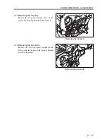
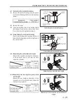
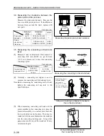
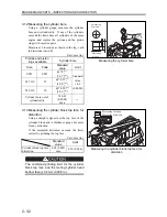
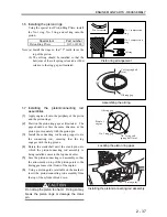
1.12 Replacing the combustion jets
Replace the combustion jets only when they are
cracked or faulty.
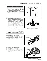
(1)
To extract the combustion jet, insert a round rod
with a diameter of approx. 6 mm (0.23 in.) into
the glow plug mounting hole and gently tap the
periphery of the combustion jet bore.
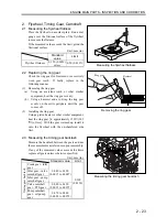
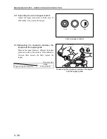
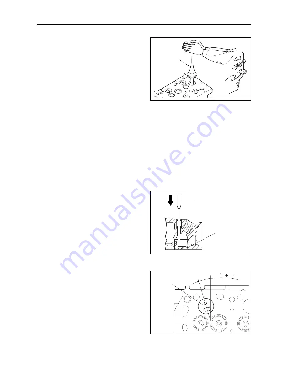
(2)
To install the jet, tap it into the mounting hole
using a plastic hammer or other similar tool.
Ensure that the nozzle hole faces the center of the
cylinder.
Lapping the valve face against the valve seat
Extracting the combustion jet
Tapping the combustion jet into place
Valve lapper
Lapping
compound
Round rod
Combustion
jet
14
30
Combustion
jet
Summary of Contents for diesel engines
Page 5: ......
Page 33: ...SERVICE STANDARDS 1 20 ...
Page 34: ...1 General Tools 1 22 2 Special Tools 1 23 TOOLS LIST ...
Page 37: ...TOOLS LIST 1 24 ...
Page 41: ...OVERHAUL TIMING 1 28 ...
Page 46: ......
Page 47: ......
Page 61: ...ENGINE MAIN PARTS DISASSEMBLY 2 16 ...
Page 99: ...FUEL SYSTEM REMOVAL 3 8 ...
Page 115: ...FUEL SYSTEM DISASSEMBLY INSPECTION AND REASSEMBLY 3 24 ...
Page 119: ...FUEL SYSTEM INSTALLATION 3 28 2 Governor Installing the governor Installation sequence ...
Page 123: ...FUEL SYSTEM INSTALLATION 3 32 ...
Page 131: ...OIL SYSTEM DISASSEMBLY INSPECTION AND REASSEMBLY 4 8 ...
Page 143: ...COOLING SYSTEM DISASSEMBLY INSPECTION AND REASSEMBLY 5 8 ...
Page 150: ......
Page 151: ......
Page 153: ...INLET AND EXHAUST SYSTEMS REMOVAL 6 4 ...
Page 159: ...INLET AND EXHAUST SYSTEMS INSTALLATION 6 10 ...
Page 160: ...1 Starter 7 2 2 Alternator 7 3 3 Stop Solenoid 7 4 4 Glow Plug 7 5 ELECTRICAL SYSTEM REMOVAL ...
Page 165: ...ELECTRICAL SYSTEM REMOVAL 7 6 ...
Page 189: ...ELECTRICAL SYSTEM INSTALLATION 7 30 ...
Page 207: ...MISCELLANEOUS 9 4 ...