

ELECTRICAL SYSTEM - DISASSEMBLY, INSPECTION AND REASSEMBLY
7 - 20
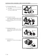
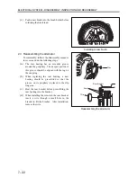
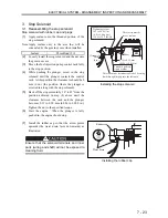
2.2 Inspecting and correcting the alternator
(1)
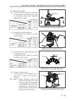
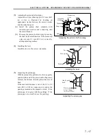
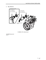
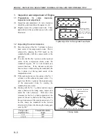
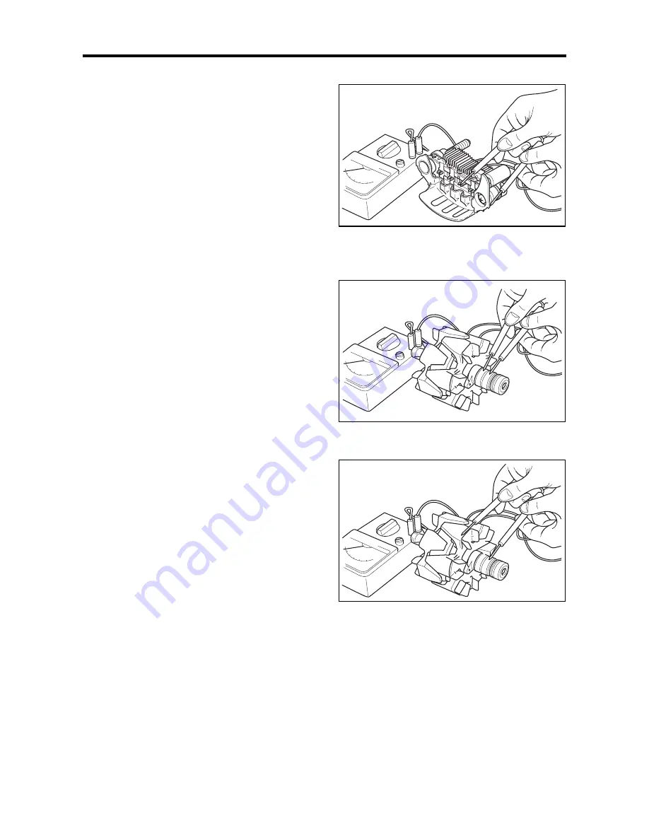
Inspecting the diodes
Perform continuity test on each of the rectifier
diodes in the following manner.
(a)
Connect a tester between the diode lead
terminal and the casing of that diode. A great
resistance should be indicated in one direction
and a small resistance in the opposite
direction.
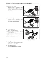
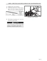
(b)
If the same level of resistance is indicated in
both directions, replace the rectifier. Perform
this test on all diodes.
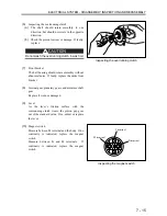
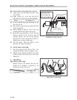
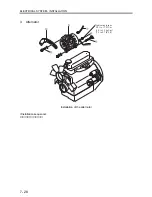
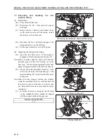
(2)
Inspecting the field coils
(a)
Measure between the slip rings. Replace if no
continuity is indicated (open circuit).
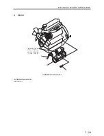
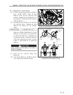
(b)
Measure between the slip ring and the shaft (or
the core). Replace if continuity is indicated.
Inspecting the diodes
Testing the field coils for open circuit
Testing the field coils for continuity
Summary of Contents for diesel engines
Page 5: ......
Page 33: ...SERVICE STANDARDS 1 20 ...
Page 34: ...1 General Tools 1 22 2 Special Tools 1 23 TOOLS LIST ...
Page 37: ...TOOLS LIST 1 24 ...
Page 41: ...OVERHAUL TIMING 1 28 ...
Page 46: ......
Page 47: ......
Page 61: ...ENGINE MAIN PARTS DISASSEMBLY 2 16 ...
Page 99: ...FUEL SYSTEM REMOVAL 3 8 ...
Page 115: ...FUEL SYSTEM DISASSEMBLY INSPECTION AND REASSEMBLY 3 24 ...
Page 119: ...FUEL SYSTEM INSTALLATION 3 28 2 Governor Installing the governor Installation sequence ...
Page 123: ...FUEL SYSTEM INSTALLATION 3 32 ...
Page 131: ...OIL SYSTEM DISASSEMBLY INSPECTION AND REASSEMBLY 4 8 ...
Page 143: ...COOLING SYSTEM DISASSEMBLY INSPECTION AND REASSEMBLY 5 8 ...
Page 150: ......
Page 151: ......
Page 153: ...INLET AND EXHAUST SYSTEMS REMOVAL 6 4 ...
Page 159: ...INLET AND EXHAUST SYSTEMS INSTALLATION 6 10 ...
Page 160: ...1 Starter 7 2 2 Alternator 7 3 3 Stop Solenoid 7 4 4 Glow Plug 7 5 ELECTRICAL SYSTEM REMOVAL ...
Page 165: ...ELECTRICAL SYSTEM REMOVAL 7 6 ...
Page 189: ...ELECTRICAL SYSTEM INSTALLATION 7 30 ...
Page 207: ...MISCELLANEOUS 9 4 ...