


ELECTRICAL SYSTEM - DISASSEMBLY, INSPECTION AND REASSEMBLY
7 - 17
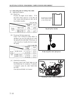
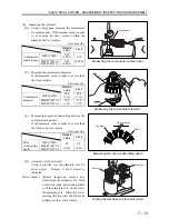
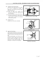
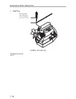
(3)
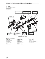
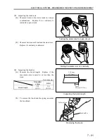
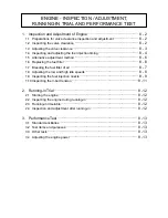
Adjusting the pinion shaft end play
Adjust the end play (thrust gap) to 0.5 mm (0.02
in.) or less as illustrated by inserting an
appropriate washer between the center bracket
and the reduction gear.
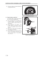
(a)
Install the pinion shaft complete with
reduction gear washers and a snap ring onto
the center bracket.
(b)
Measure the pinion shaft end play by moving
the shaft in the axial direction. If the measured
value exceeds 0.5 mm (0.02 in.), correct by
adding adjusting washers.
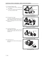
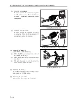
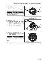
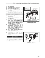
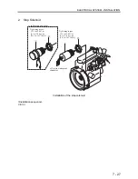
(4)
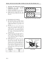
Installing
the
lever
Install the lever in the correct orientation.
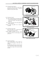
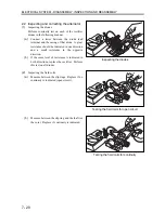
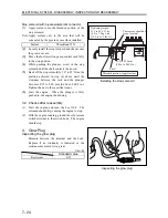
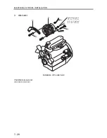
(5)
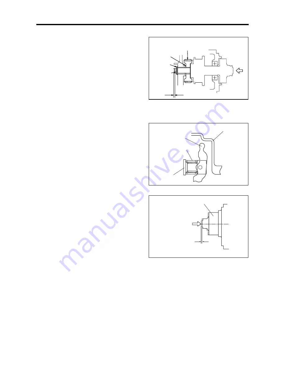
Inspecting the pinion gap
With the pinion fully pulled out to the rear, gently
push back the end of the pinion with a finger and
measure the distance that the pinion has moved
back.
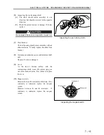
If the measured distance is out of the 0.5 to 2.0
mm (0.02 to 0.08 in.) range, add or reduce the
packings mounted at the magnetic switch. If the
pinion gap is too great, add the packings. If the
pinion gap is too small, reduce the packings.
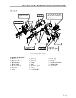
Adjusting the pinion shaft end play
Installing the lever
Adjusting the pinion gap
Max. 0.5 mm (0.02 in.)
End play
Snap ring
Washer
Adjusting
washer
Reduction
gear
Front bracket
Lever
Lever spring
Packing
Gently push
back.
Pinion gap
0.5 to 2.0 mm
(0.02 to 0.08 in.)
Pinion
Summary of Contents for diesel engines
Page 5: ......
Page 33: ...SERVICE STANDARDS 1 20 ...
Page 34: ...1 General Tools 1 22 2 Special Tools 1 23 TOOLS LIST ...
Page 37: ...TOOLS LIST 1 24 ...
Page 41: ...OVERHAUL TIMING 1 28 ...
Page 46: ......
Page 47: ......
Page 61: ...ENGINE MAIN PARTS DISASSEMBLY 2 16 ...
Page 99: ...FUEL SYSTEM REMOVAL 3 8 ...
Page 115: ...FUEL SYSTEM DISASSEMBLY INSPECTION AND REASSEMBLY 3 24 ...
Page 119: ...FUEL SYSTEM INSTALLATION 3 28 2 Governor Installing the governor Installation sequence ...
Page 123: ...FUEL SYSTEM INSTALLATION 3 32 ...
Page 131: ...OIL SYSTEM DISASSEMBLY INSPECTION AND REASSEMBLY 4 8 ...
Page 143: ...COOLING SYSTEM DISASSEMBLY INSPECTION AND REASSEMBLY 5 8 ...
Page 150: ......
Page 151: ......
Page 153: ...INLET AND EXHAUST SYSTEMS REMOVAL 6 4 ...
Page 159: ...INLET AND EXHAUST SYSTEMS INSTALLATION 6 10 ...
Page 160: ...1 Starter 7 2 2 Alternator 7 3 3 Stop Solenoid 7 4 4 Glow Plug 7 5 ELECTRICAL SYSTEM REMOVAL ...
Page 165: ...ELECTRICAL SYSTEM REMOVAL 7 6 ...
Page 189: ...ELECTRICAL SYSTEM INSTALLATION 7 30 ...
Page 207: ...MISCELLANEOUS 9 4 ...