
ELECTRICAL SYSTEM - DISASSEMBLY, INSPECTION AND REASSEMBLY
7 - 22
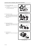
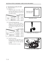
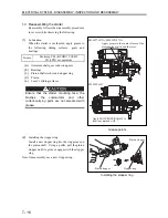
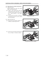
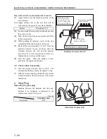
(c)
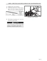
Push a new brush into the brush holder before
soldering the brush lead.
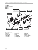
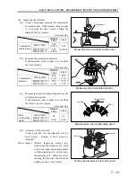
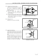
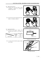
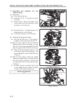
2.3 Reassembling the alternator
To reassembly, follows the disassembly sequence
in reverse and do the following steps.
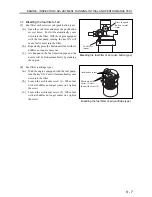
(a)
The rear bearing has an eccentric groove
around the periphery. The deepest portion of
this groove should be aligned with the lug on
the snap ring.
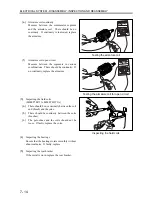
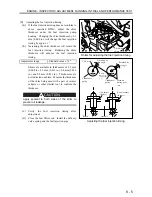
(b)
When replacing the rear bearing, a new
bearing should be press-fitted so that the
groove on its periphery is placed to the slip
ring side.
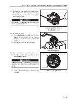
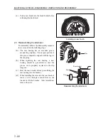
(c)
Heat the rear bracket before press-fitting the
rear bearing into the bracket.
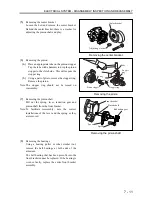
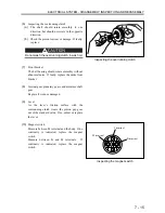
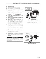
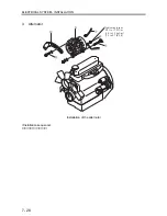
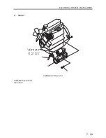
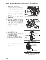
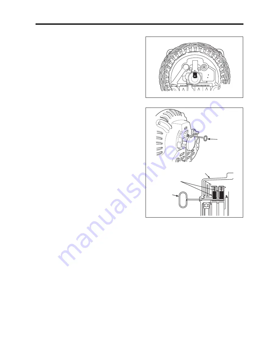
(d)
When installing the rotor into the rear bracket,
insert a wire through a small hole in the
bracket to lift the brushes. After installation,
remove the wire.
Installing a new brush
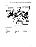
Reassembling the alternator
Rear bracket
Brush
Wire
Wire
Summary of Contents for diesel engines
Page 5: ......
Page 33: ...SERVICE STANDARDS 1 20 ...
Page 34: ...1 General Tools 1 22 2 Special Tools 1 23 TOOLS LIST ...
Page 37: ...TOOLS LIST 1 24 ...
Page 41: ...OVERHAUL TIMING 1 28 ...
Page 46: ......
Page 47: ......
Page 61: ...ENGINE MAIN PARTS DISASSEMBLY 2 16 ...
Page 99: ...FUEL SYSTEM REMOVAL 3 8 ...
Page 115: ...FUEL SYSTEM DISASSEMBLY INSPECTION AND REASSEMBLY 3 24 ...
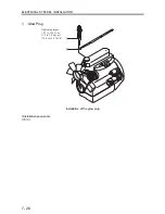
Page 119: ...FUEL SYSTEM INSTALLATION 3 28 2 Governor Installing the governor Installation sequence ...
Page 123: ...FUEL SYSTEM INSTALLATION 3 32 ...
Page 131: ...OIL SYSTEM DISASSEMBLY INSPECTION AND REASSEMBLY 4 8 ...
Page 143: ...COOLING SYSTEM DISASSEMBLY INSPECTION AND REASSEMBLY 5 8 ...
Page 150: ......
Page 151: ......
Page 153: ...INLET AND EXHAUST SYSTEMS REMOVAL 6 4 ...
Page 159: ...INLET AND EXHAUST SYSTEMS INSTALLATION 6 10 ...
Page 160: ...1 Starter 7 2 2 Alternator 7 3 3 Stop Solenoid 7 4 4 Glow Plug 7 5 ELECTRICAL SYSTEM REMOVAL ...
Page 165: ...ELECTRICAL SYSTEM REMOVAL 7 6 ...
Page 189: ...ELECTRICAL SYSTEM INSTALLATION 7 30 ...
Page 207: ...MISCELLANEOUS 9 4 ...