ENGINE MAIN PARTS - INSPECTION AND CORRECTION
2 - 19
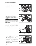
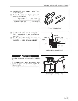
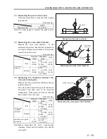
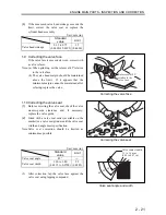
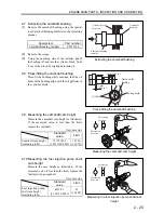
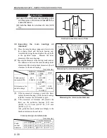
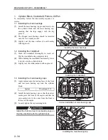
1.4 Measuring the push rod for bend
If the measured value exceeds the limit, replace
the push rod.
Unit: mm (in.)
Limit
Push rod bend
0.3 (0.012)
Note: Use a dial gauge to measure the push rod for
bend.
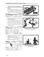
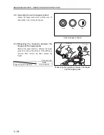
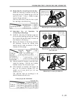
1.5 Measuring the valve stem diameter
Measure the valve stem diameter. If the
measured value is less than the limit, replace with
a new part. Replace also when the valve stem has
excessively uneven wear.
Unit: mm (in.)
Nominal
value
Standard
value
Limit
Inlet
φ
6.6
(0.260)
6.565
to 6.580
(0.2586
to 0.2592)
6.500
(0.256)
Valve stem
diameter
Exhaust
φ
6.6
(0.260)
6.530
to 6.550
(0.2572
to 0.2580)
6.500
(0.256)
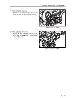
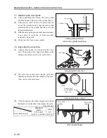
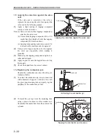
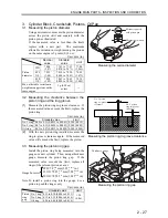
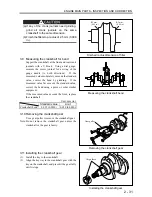
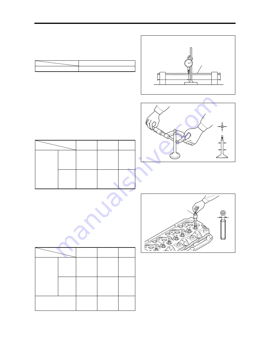
1.6 Measuring the clearance between the
valve stem and guide
Measure the valve guide inner diameter using an
inside micrometer.
The valve guide wears at the top and bottom ends.
Therefore, both ends need to be measured
orthogonally. If the measured value exceeds the
limit, replace with a new part.
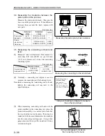
Unit: mm (in.)
Nominal
value
Standard
value
Limit
Inlet
―
0.020
to 0.050
(0.0008
to 0.002)
0.100
(0.004)
Valve stem
-to-guide
clearance
Exhaust
―
0.050
to 0.085
(0.002
to 0.003)
0.150
(0.006)
Installed valve guide
protrusion
10
(0.394)
9.5 to 10.5
(0.3743
to 0.4137)
―
Note:
Before measuring the valve stem-to-guide
clearance, remove carbon from the valve and the
valve guide.
Measuring the valve stem diameter
Measuring the push rod bend
1/2
1/2
Push rod
Measuring the valve guide inner diameter
Measuring
direction
Measuring
location
Inside micrometer
Measuring
direction
Measuring
location
Summary of Contents for diesel engines
Page 5: ......
Page 33: ...SERVICE STANDARDS 1 20 ...
Page 34: ...1 General Tools 1 22 2 Special Tools 1 23 TOOLS LIST ...
Page 37: ...TOOLS LIST 1 24 ...
Page 41: ...OVERHAUL TIMING 1 28 ...
Page 46: ......
Page 47: ......
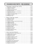
Page 61: ...ENGINE MAIN PARTS DISASSEMBLY 2 16 ...
Page 99: ...FUEL SYSTEM REMOVAL 3 8 ...
Page 115: ...FUEL SYSTEM DISASSEMBLY INSPECTION AND REASSEMBLY 3 24 ...
Page 119: ...FUEL SYSTEM INSTALLATION 3 28 2 Governor Installing the governor Installation sequence ...
Page 123: ...FUEL SYSTEM INSTALLATION 3 32 ...
Page 131: ...OIL SYSTEM DISASSEMBLY INSPECTION AND REASSEMBLY 4 8 ...
Page 143: ...COOLING SYSTEM DISASSEMBLY INSPECTION AND REASSEMBLY 5 8 ...
Page 150: ......
Page 151: ......
Page 153: ...INLET AND EXHAUST SYSTEMS REMOVAL 6 4 ...
Page 159: ...INLET AND EXHAUST SYSTEMS INSTALLATION 6 10 ...
Page 160: ...1 Starter 7 2 2 Alternator 7 3 3 Stop Solenoid 7 4 4 Glow Plug 7 5 ELECTRICAL SYSTEM REMOVAL ...
Page 165: ...ELECTRICAL SYSTEM REMOVAL 7 6 ...
Page 189: ...ELECTRICAL SYSTEM INSTALLATION 7 30 ...
Page 207: ...MISCELLANEOUS 9 4 ...