SERVICE STANDARDS
1 - 13
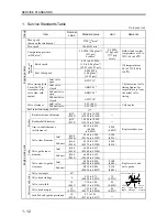
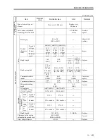
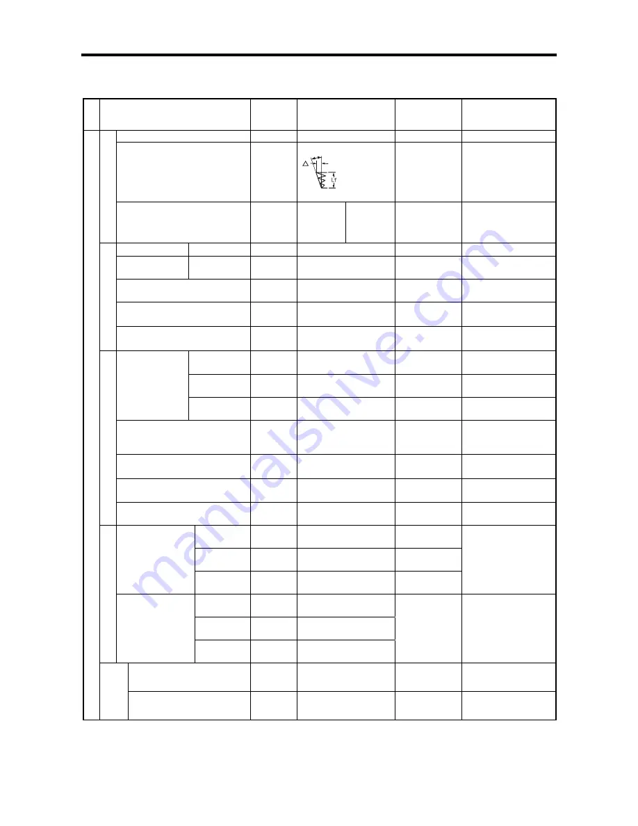
Unit: mm (in.)
Gro
up
Item
Nominal
value
Standard value
Limit
Remarks
Free length
47 (1.85)
46 (1.81)
Squareness
θ
=2.0°
Δ
=0.2
(0.0079)
Lf=47
(1.8518)
△
= 0.5
(0.0197)
across the
entire length
V
al
ve s
pri
ng
Installed length
/
load
mm (in.)/N (kgf) [lbf]
39.0 (1.536)/
131 to 145
(13.3 to 14.7)
[29 to 33]
30.1 (1.185)/
279 to 309
(28.5 to 31.5)
[63 to 69]
-15 %
Push rod
Bend
―
0.3 (0.011)
Replace
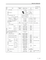
Cylinder head
Bottom face
distortion
0.05 (0.002)
or less
0.10 (0.004)
Correct
Cylinder block top face
distortion
0.05 (0.002)
or less
0.10 (0.004)
Correct
Bore
φ
78
(3.07)
78.0
+0.03
0
(3.07
+0.0012
0
)
78.2 (3.08)
Bore or replace
C
yl
inde
r
Out of roundness
±
0.01 (0.0004)
or less
―
STD
78.00
(3.07)
77.93 to 77.95
(3.070 to 3.071)
77.80
(3.065)
0.25 OS
78.25
(3.08)
78.18 to 78.20
(3.080 to 3.081)
78.05
(3.075)
Diameter
0.50 OS
78.50
(3.09)
78.43 to 78.45
(3.090 to 3.090)
78.30
(3.085)
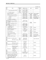
Max. allowable variation in
weight among pistons on the
same engine
±
5 g (0.177 oz)
or less
―
Piston pin diameter
φ
23
(0.9062)
22.944 to 23.000
(0.9039 to 0.9062)
―
Piston pin-to-boss clearance
0.006 to 0.018
(0.0002 to 0.0007)
0.050
(0.002)
Pi
st
on
Piston-to-cylinder clearance
0.035 to 0.086
(0.0014 to 0.0034)
0.300
(0.012)
Bore or replace
No. 1 ring
0.09 to 0.11
(0.0035 to 0.0043)
0.300
(0.012)
No. 2 ring
0.07 to 0.11
(0.0028 to 0.0043)
0.200
(0.008)
Piston
ring-to-groove
clearance
Oil ring
0.03 to 0.07
(0.0012 to 0.0028)
0.200
(0.008)
Replace piston ring
No. 1 ring
0.15 to 0.30
(0.006 to 0.012)
No. 2 ring
0.15 to 0.35
(0.006 to 0.014)
Piston ring
Piston ring gap
Oil ring
0.20 to 0.40
(0.008 to 0.016)
1.50
(0.06)
Replace
Bend and twist
0.05/100
(0.002/3.940)
0.15/100
(0.006/3.940)
Engine mai
n
p
a
rt
s
Co
nn
ecting
ro
d
End play
0.10 to 0.35
(0.004 to 0.014)
0.50
(0.020)
Replace connecting
rod
θ
Summary of Contents for diesel engines
Page 5: ......
Page 33: ...SERVICE STANDARDS 1 20 ...
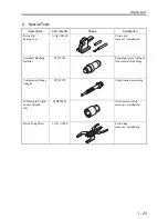
Page 34: ...1 General Tools 1 22 2 Special Tools 1 23 TOOLS LIST ...
Page 37: ...TOOLS LIST 1 24 ...
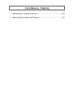
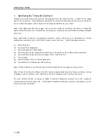
Page 41: ...OVERHAUL TIMING 1 28 ...
Page 46: ......
Page 47: ......
Page 61: ...ENGINE MAIN PARTS DISASSEMBLY 2 16 ...
Page 99: ...FUEL SYSTEM REMOVAL 3 8 ...
Page 115: ...FUEL SYSTEM DISASSEMBLY INSPECTION AND REASSEMBLY 3 24 ...
Page 119: ...FUEL SYSTEM INSTALLATION 3 28 2 Governor Installing the governor Installation sequence ...
Page 123: ...FUEL SYSTEM INSTALLATION 3 32 ...
Page 131: ...OIL SYSTEM DISASSEMBLY INSPECTION AND REASSEMBLY 4 8 ...
Page 143: ...COOLING SYSTEM DISASSEMBLY INSPECTION AND REASSEMBLY 5 8 ...
Page 150: ......
Page 151: ......
Page 153: ...INLET AND EXHAUST SYSTEMS REMOVAL 6 4 ...
Page 159: ...INLET AND EXHAUST SYSTEMS INSTALLATION 6 10 ...
Page 160: ...1 Starter 7 2 2 Alternator 7 3 3 Stop Solenoid 7 4 4 Glow Plug 7 5 ELECTRICAL SYSTEM REMOVAL ...
Page 165: ...ELECTRICAL SYSTEM REMOVAL 7 6 ...
Page 189: ...ELECTRICAL SYSTEM INSTALLATION 7 30 ...
Page 207: ...MISCELLANEOUS 9 4 ...

