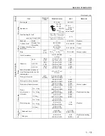

SERVICE STANDARDS
1 - 15
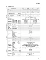
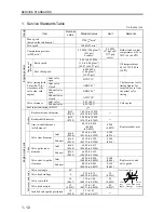
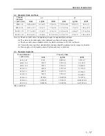
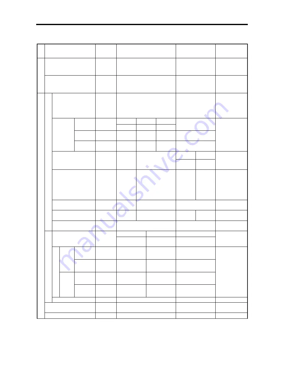
Unit: mm (in.)
Gro
up
Item
Nominal
value
Standard value
Limit
Remarks
Paper-element type air
cleaner
Clean every 100 hours
Replace every
500 hours
In
le
t an
d
ex
h
aus
t
s
y
st
em
s
Inlet
/
exhaust manifold
mounting face distortion
―
0.15 (0.006)
or less
Grind or
replace
Pinion gap
0.5 to 2.0
(0.02 to 0.08)
―
Adjust with
packing
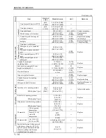
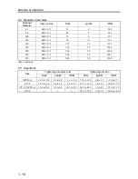
M001T68281 M008T70471A M008T81071A
Terminal
voltage
11 V
11 V
23 V
―
Current
110 A
or less
130 A
or less
80 A
or less
―
No-load
character-
istics
Rotation
speed
2400
min
-1
3600
min
-1
3000
min
-1
―
Inspect
M001T68281
M008T70471A,
M008T81071A
Brush length
16.5
(0.65)
18.0
(0.71)
10.0
(0.39)
11.0
(0.43)
Replace
Brush spring load
17.5 to
23.7 N
(1.78 to
2.41 kgf)
[3.9 to 5.3
lbf]
29.4 to 39.2 N
(3.0 to 4.0 kgf)
[6.6 to 8.8 lbf]
6.90 N
(0.70 kgf)
[1.6 lbf]
13.7 N
(1.40 kgf)
[3.1 lbf]
Replace
Commutator radial
runout
0.05
(0.002)
0.03
(0.001)
0.10
(0.004)
Correct or
replace
Commutator diameter
29.4
(1.16)
32.0
(1.26)
28.8
(1.13)
31.4
(1.24)
Replace
St
ar
te
r
Mica undercutting
depth
0.5
(0.02)
0.2
(0.01)
Correct
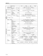
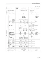
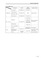
A007T02071C A007TA8571
―
IC regulator
controlled voltage
[at 20
℃
(68
°
F
)]
14.7
±
0.3 V
28.5
±
0.5 V
Terminal
voltage
13.5 V
27.0 V
―
2500
min
-1
or
less
Current
32 A or above
18 A or above
―
Terminal
voltage
13.5 V
27.0 V
―
O
ut
put
c
ha
racter
ist
ics
(w
he
n hot
)
5000
min
-1
or
less
Current
47 A or above
22 A or above
―
Altern
at
or
Brush length
18.5 (0.73) 5.0
(0.20)
Replace
Clearance between stop
solenoid plunger and rack
0.15 to 0.20
(0.006 to 0.008)
Correct
Elec
tric
al sys
tem
Glow plug resistance
0.55
Ω
―
Replace
Summary of Contents for diesel engines
Page 5: ......
Page 33: ...SERVICE STANDARDS 1 20 ...
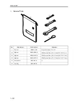
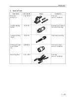
Page 34: ...1 General Tools 1 22 2 Special Tools 1 23 TOOLS LIST ...
Page 37: ...TOOLS LIST 1 24 ...
Page 41: ...OVERHAUL TIMING 1 28 ...
Page 46: ......
Page 47: ......
Page 61: ...ENGINE MAIN PARTS DISASSEMBLY 2 16 ...
Page 99: ...FUEL SYSTEM REMOVAL 3 8 ...
Page 115: ...FUEL SYSTEM DISASSEMBLY INSPECTION AND REASSEMBLY 3 24 ...
Page 119: ...FUEL SYSTEM INSTALLATION 3 28 2 Governor Installing the governor Installation sequence ...
Page 123: ...FUEL SYSTEM INSTALLATION 3 32 ...
Page 131: ...OIL SYSTEM DISASSEMBLY INSPECTION AND REASSEMBLY 4 8 ...
Page 143: ...COOLING SYSTEM DISASSEMBLY INSPECTION AND REASSEMBLY 5 8 ...
Page 150: ......
Page 151: ......
Page 153: ...INLET AND EXHAUST SYSTEMS REMOVAL 6 4 ...
Page 159: ...INLET AND EXHAUST SYSTEMS INSTALLATION 6 10 ...
Page 160: ...1 Starter 7 2 2 Alternator 7 3 3 Stop Solenoid 7 4 4 Glow Plug 7 5 ELECTRICAL SYSTEM REMOVAL ...
Page 165: ...ELECTRICAL SYSTEM REMOVAL 7 6 ...
Page 189: ...ELECTRICAL SYSTEM INSTALLATION 7 30 ...
Page 207: ...MISCELLANEOUS 9 4 ...


