

ENGINE - INSPECTION
/
ADJUSTMENT, RUNNING-IN TRIAL AND PERFORMANCE TEST
8 - 5
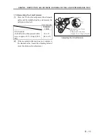
(3)
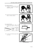
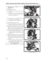
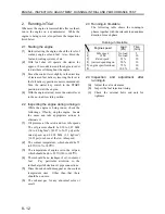
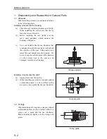
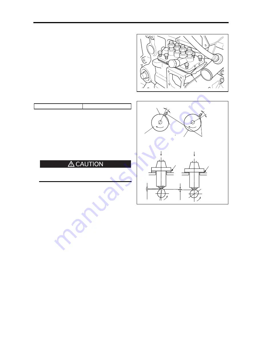
Adjusting the fuel injection timing
(a)
If the fuel injection timing does not conform to
above specified BTDC, adjust the shim
thickness under the fuel injection pump
housing. Changing the shim thickness by 0.1
mm (0.004 in.) will change the fuel injection
timing by approx. 1°
(b)
Increasing the shim thickness will retard the
fuel injection timing. Reducing the shim
thickness will advance the fuel injection
timing.
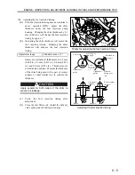
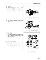
Adjustment range
Standard value ±1.5º
Shims are available in thicknesses of 0.2 mm
(0.008 in.), 0.3 mm (0.012 in.), 0.4 mm (0.016
in.) and 0.8 mm (0.031 in.). Thicknesses are
not indicated on shims. Measure the thickness
of the shim being used with a pair of vernier
calipers or other similar tool to confirm the
thickness.
Apply sealant to both sides of the shim to
prevent oil leakage.
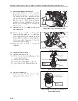
(c)
Verify the fuel injection timing after
adjustment.
(d)
Close the fuel filter cock. Install the delivery
valve spring and the fuel injection pipe.
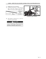
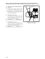
Shims for adjusting the fuel injection timing
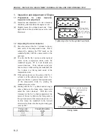
Adjusting the fuel injection timing
Adjusting
shims
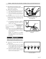
Advanced by
this angle
TDC mark
Retarded by
this angle
IT mark
(One division
corresponds
to 2 )
Crankshaft
pulley
Crankshaft
pulley
Add shims
(thicker)
Reduce shims
(thinner)
Advance
Retard
Mark on
timing gear
case
Summary of Contents for diesel engines
Page 5: ......
Page 33: ...SERVICE STANDARDS 1 20 ...
Page 34: ...1 General Tools 1 22 2 Special Tools 1 23 TOOLS LIST ...
Page 37: ...TOOLS LIST 1 24 ...
Page 41: ...OVERHAUL TIMING 1 28 ...
Page 46: ......
Page 47: ......
Page 61: ...ENGINE MAIN PARTS DISASSEMBLY 2 16 ...
Page 99: ...FUEL SYSTEM REMOVAL 3 8 ...
Page 115: ...FUEL SYSTEM DISASSEMBLY INSPECTION AND REASSEMBLY 3 24 ...
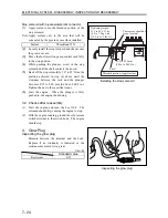
Page 119: ...FUEL SYSTEM INSTALLATION 3 28 2 Governor Installing the governor Installation sequence ...
Page 123: ...FUEL SYSTEM INSTALLATION 3 32 ...
Page 131: ...OIL SYSTEM DISASSEMBLY INSPECTION AND REASSEMBLY 4 8 ...
Page 143: ...COOLING SYSTEM DISASSEMBLY INSPECTION AND REASSEMBLY 5 8 ...
Page 150: ......
Page 151: ......
Page 153: ...INLET AND EXHAUST SYSTEMS REMOVAL 6 4 ...
Page 159: ...INLET AND EXHAUST SYSTEMS INSTALLATION 6 10 ...
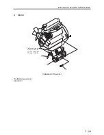
Page 160: ...1 Starter 7 2 2 Alternator 7 3 3 Stop Solenoid 7 4 4 Glow Plug 7 5 ELECTRICAL SYSTEM REMOVAL ...
Page 165: ...ELECTRICAL SYSTEM REMOVAL 7 6 ...
Page 189: ...ELECTRICAL SYSTEM INSTALLATION 7 30 ...
Page 207: ...MISCELLANEOUS 9 4 ...


