ENGINE MAIN PARTS - INSPECTION AND CORRECTION
2 - 31
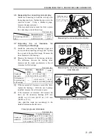
(a) If any of the crank journals need grinding,
grind all crank journals on the same
crankshaft to the same dimension.
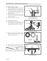
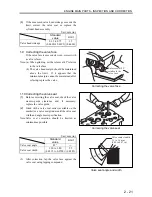
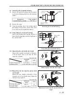
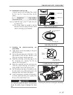
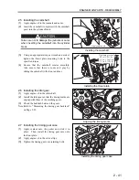
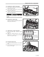
(b) Finish the fillets to a radius of 2.5 mm (0.098
in.).
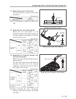
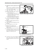
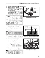
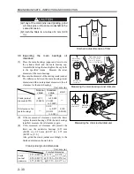
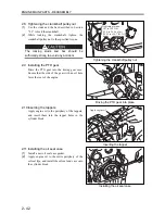
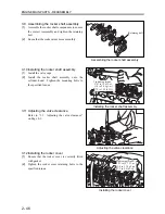
3.9 Measuring the crankshaft for bend
Support the crankshaft at the front and rear crank
journals with a V block. Using a dial gauge,
measure the center journal for a swing of the
gauge needle (to both directions). If the
measured value moderately exceeds the standard
value, correct the bend by grinding. If the
measured value far exceeds the standard value,
correct the bend using a press or other similar
equipment.
If the measured value exceeds the limit, replace
the crankshaft.
Unit: mm (in.)
Standard value
Limit
Crankshaft bend
0.025 (0.0010)
0.050 (0.0020)
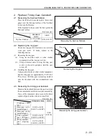
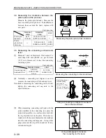
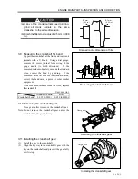
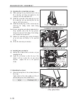
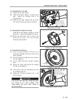
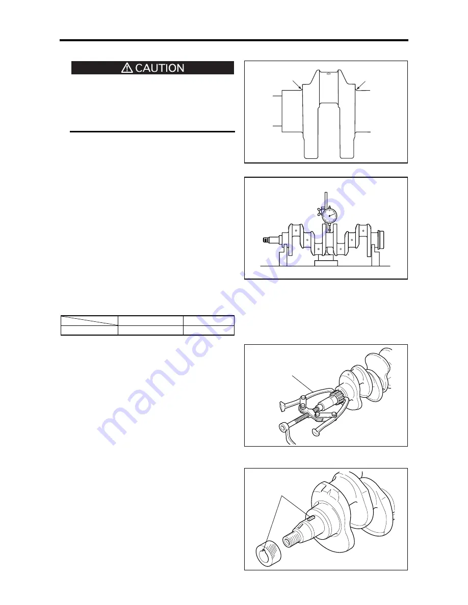
3.10 Removing the crankshaft gear
Use a gear puller to remove the crankshaft gear.
Note: Do not remove the crankshaft gear unless the
crankshaft or the gear is faulty.
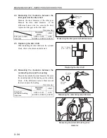
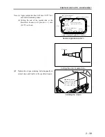
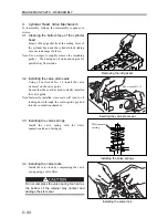
3.11 Installing the crankshaft gear
(1)
Install the key to the crankshaft.
(2) Align the keyway in the crankshaft gear with the
key on the crankshaft, and press-fit the gear fully
until it stops.
Finished radius dimension of fillet
Measuring the crankshaft bend
Removing the crankshaft gear
Installing the crankshaft gear
Gear puller
R2 mm
(0.08 in.)
R2 mm
(0.08 in.)
Align these
Summary of Contents for diesel engines
Page 5: ......
Page 33: ...SERVICE STANDARDS 1 20 ...
Page 34: ...1 General Tools 1 22 2 Special Tools 1 23 TOOLS LIST ...
Page 37: ...TOOLS LIST 1 24 ...
Page 41: ...OVERHAUL TIMING 1 28 ...
Page 46: ......
Page 47: ......
Page 61: ...ENGINE MAIN PARTS DISASSEMBLY 2 16 ...
Page 99: ...FUEL SYSTEM REMOVAL 3 8 ...
Page 115: ...FUEL SYSTEM DISASSEMBLY INSPECTION AND REASSEMBLY 3 24 ...
Page 119: ...FUEL SYSTEM INSTALLATION 3 28 2 Governor Installing the governor Installation sequence ...
Page 123: ...FUEL SYSTEM INSTALLATION 3 32 ...
Page 131: ...OIL SYSTEM DISASSEMBLY INSPECTION AND REASSEMBLY 4 8 ...
Page 143: ...COOLING SYSTEM DISASSEMBLY INSPECTION AND REASSEMBLY 5 8 ...
Page 150: ......
Page 151: ......
Page 153: ...INLET AND EXHAUST SYSTEMS REMOVAL 6 4 ...
Page 159: ...INLET AND EXHAUST SYSTEMS INSTALLATION 6 10 ...
Page 160: ...1 Starter 7 2 2 Alternator 7 3 3 Stop Solenoid 7 4 4 Glow Plug 7 5 ELECTRICAL SYSTEM REMOVAL ...
Page 165: ...ELECTRICAL SYSTEM REMOVAL 7 6 ...
Page 189: ...ELECTRICAL SYSTEM INSTALLATION 7 30 ...
Page 207: ...MISCELLANEOUS 9 4 ...