


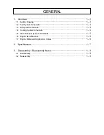
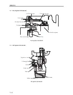
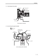

GENERAL
1 - 7
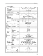
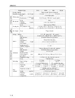
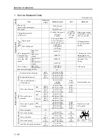
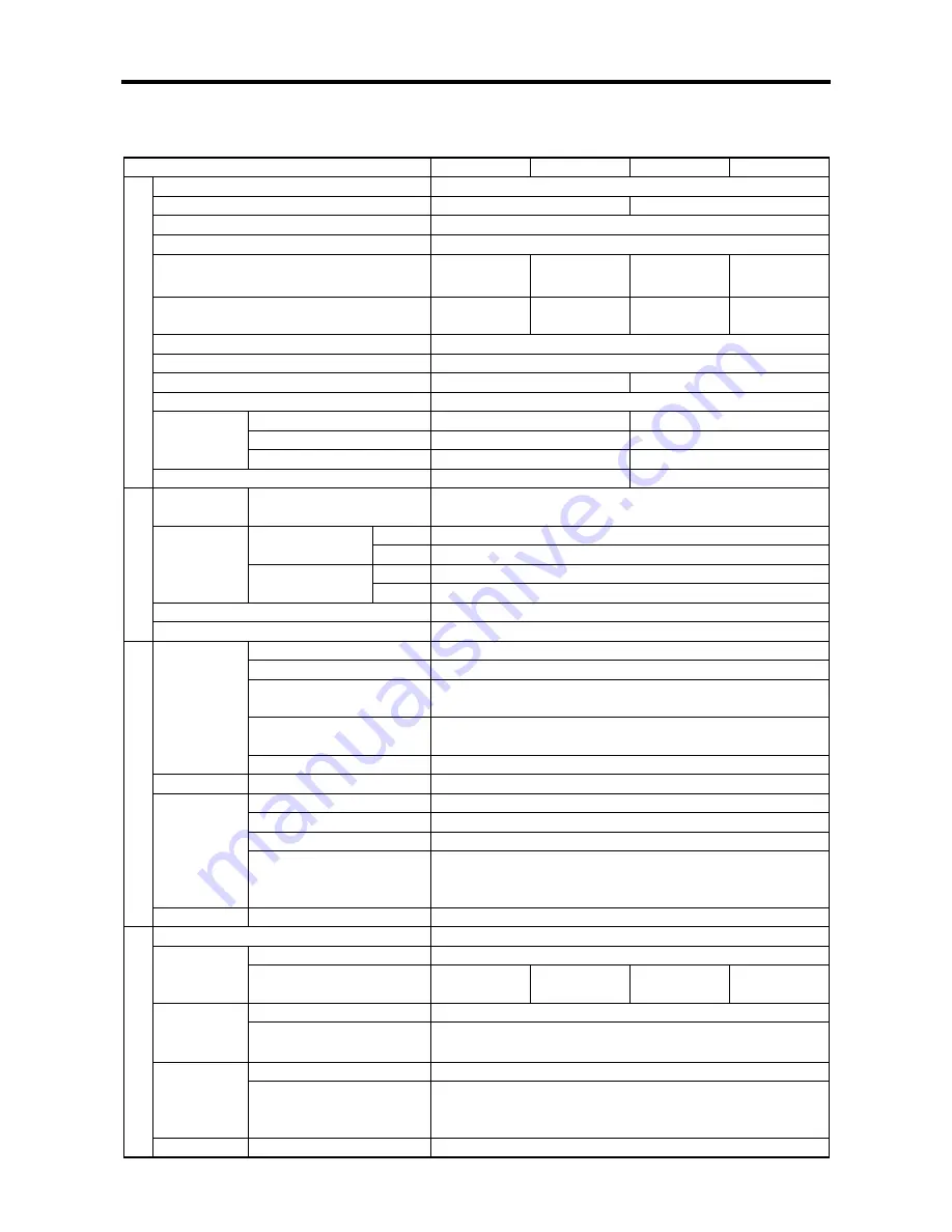
2. Specifications
Engine
Type
S3L S3L2 S4L S4L2
Type
Water-cooled; 4-stroke cycle; Diesel powered
No. of cylinders
3
4
Combustion
Swirl chamber type
Valve mechanism
Overhead valve type
Cylinder bore
×
stroke mm
(in.)
78
×
78.5
(3.07
×
3.09)
78
×
92
(3.07
×
3.62)
78
×
78.5
(3.07
×
3.09)
78
×
92
(3.07
×
3.62)
Total displacement
l
(U.S. gal)
1.125
(0.297)
1.318
(0.348)
1.500
(0.396)
1.758
(0.464)
Compression ratio
22.0 : 1
Fuel
Diesel fuel (JIS K2204 Special 1 - 3)
Firing order
1-3-2
1-3-4-2
Direction of rotation
Counterclockwise when viewed from the flywheel end
Overall length mm (in.)
536 (21.10)
620 (24.40)
Overall width mm (in.)
433 (17.04)
433 (17.04)
Dimensions
Overall height mm (in.)
572 (22.52)
572 (22.52)
General
Dry mass
kg (lb)
135 (297.6)
155 (341.7)
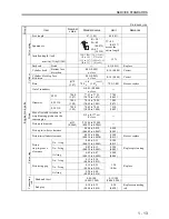
Piston ring
No. of rings
Compression ring :2
Oil ring (w/expander) : 1
Open BTDC
15°
Inlet valve
Close ABDC
41°
Open BBDC
54°
Valve
timing
(hot engine) Exhaust valve
Close ATDC
10°
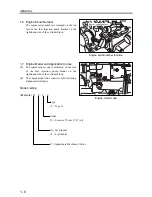
Engine mounting
4 mounts
Engine main p
a
rt
s
Starting method
Starter
Type Bosch
M
Manufacturer DENSO
Plunger
diameter
mm (in.)
φ
5.5 (0.21)
MS retard
(crank angle)
8°
Injection
pump
Cam lift
mm(in.)
15 (0.59)
Governor Governing
method
Centrifugal fly-weight type
Type Throttle
nozzle
Manufacturer Bosch
Automotive Systems Corporation
Spray angle
mm (in.)
15°
Injection
nozzle
Opening
pressure
MPa
(kgf/cm
2
)
[psi]
14.22 to 15.00 (145 to 153)
[2062 to 2176]
Fuel system
Fuel filter
Type
Paper-element cartridge; Separate type w/ cock
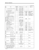
Lubrication method
Forced circulation (pressure feed by trochoid pump)
Grade
CD Class (API Classification)
Engine oil
Capacity
(entire engine)
l
(U.S. gal)
3.7 (1.0)
4.2 (1.1)
5.4 (1.4)
6.0 (1.6)
Type Gear
pump
Oil pump
Displacement
l
(U.S. gal)
/min
18 (4.8)
Type Piston
valve
Relief valve Opening
pressure
MPa
(kgf/cm
2
)
[psi]
0.35
±
0.05 (3.6
±
0.5)
[51
±
7]
Oil system
Oil filter
Type
Paper element (spin-on type)
Summary of Contents for diesel engines
Page 5: ......
Page 33: ...SERVICE STANDARDS 1 20 ...
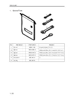
Page 34: ...1 General Tools 1 22 2 Special Tools 1 23 TOOLS LIST ...
Page 37: ...TOOLS LIST 1 24 ...
Page 41: ...OVERHAUL TIMING 1 28 ...
Page 46: ......
Page 47: ......
Page 61: ...ENGINE MAIN PARTS DISASSEMBLY 2 16 ...
Page 99: ...FUEL SYSTEM REMOVAL 3 8 ...
Page 115: ...FUEL SYSTEM DISASSEMBLY INSPECTION AND REASSEMBLY 3 24 ...
Page 119: ...FUEL SYSTEM INSTALLATION 3 28 2 Governor Installing the governor Installation sequence ...
Page 123: ...FUEL SYSTEM INSTALLATION 3 32 ...
Page 131: ...OIL SYSTEM DISASSEMBLY INSPECTION AND REASSEMBLY 4 8 ...
Page 143: ...COOLING SYSTEM DISASSEMBLY INSPECTION AND REASSEMBLY 5 8 ...
Page 150: ......
Page 151: ......
Page 153: ...INLET AND EXHAUST SYSTEMS REMOVAL 6 4 ...
Page 159: ...INLET AND EXHAUST SYSTEMS INSTALLATION 6 10 ...
Page 160: ...1 Starter 7 2 2 Alternator 7 3 3 Stop Solenoid 7 4 4 Glow Plug 7 5 ELECTRICAL SYSTEM REMOVAL ...
Page 165: ...ELECTRICAL SYSTEM REMOVAL 7 6 ...
Page 189: ...ELECTRICAL SYSTEM INSTALLATION 7 30 ...
Page 207: ...MISCELLANEOUS 9 4 ...