FUEL SYSTEM - DISASSEMBLY, INSPECTION AND REASSEMBLY
3 - 11
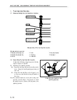
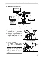
(c)
If the measured pressure does not conform to
the standard value, disassemble and adjust by
changing the thickness of the washer.
Unit: MPa (kgf/cm
2
) [psi]
Standard
value
Injection valve opening
pressure
14.22 to 15.00
(145 to 153)
[2062 to 2176]
(d)
Change in washer thickness by 0.1 mm (0.004
in.) results in a pressure change of 1.0 MPa (10
kgf/cm
2
) [145 psi].
Washers are available in 10 different
thicknesses at intervals of 0.05 mm (0.002 in.)
in the range between 1.25 and 1.70 mm (0.049
and 0.067 in.).
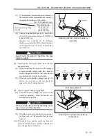
Never touch the spray of fuel from the fuel
injection nozzle.
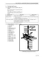
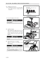
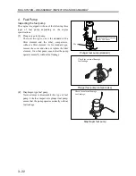
(2)
Inspecting the fuel spray pattern from the fuel
injection nozzle
(a)
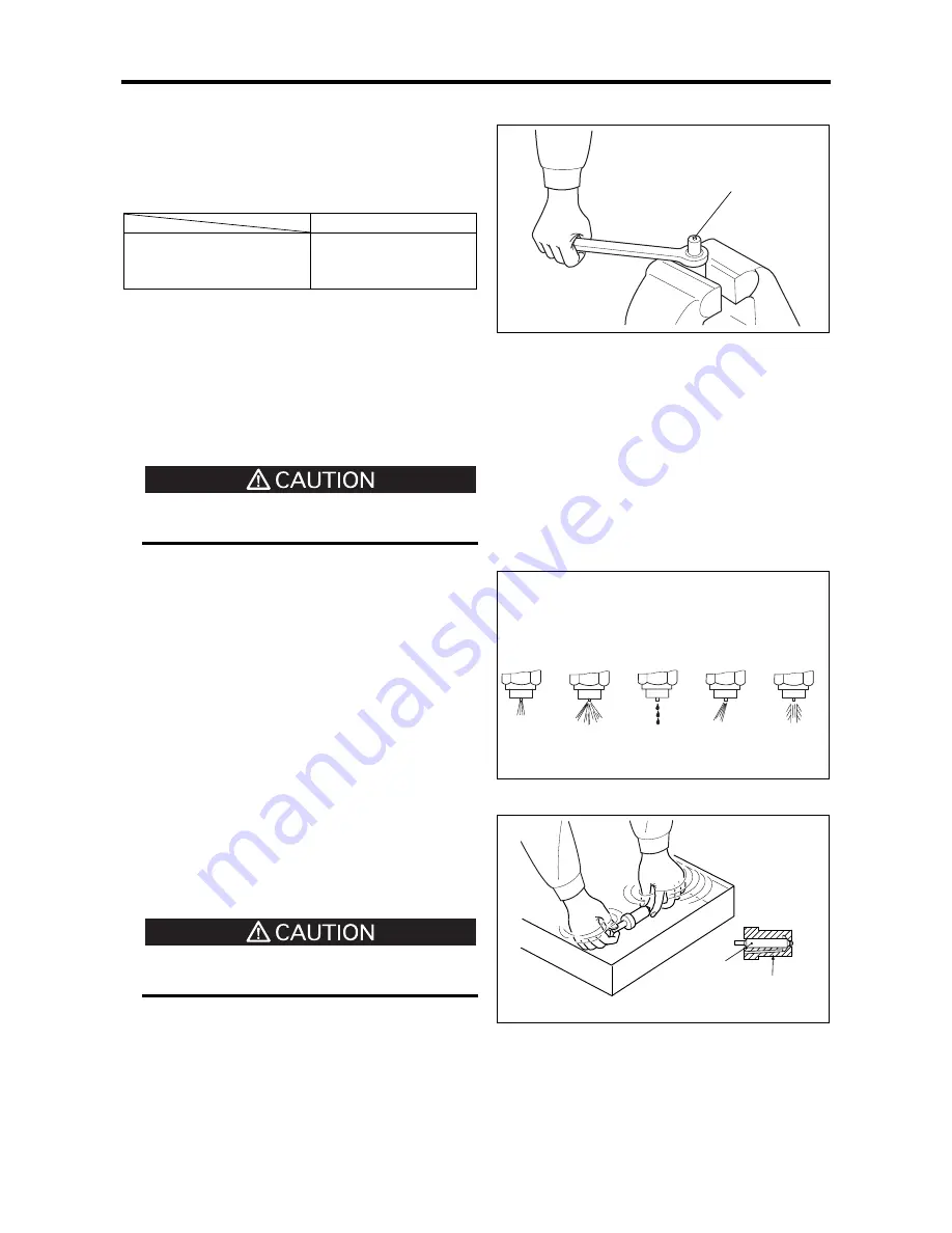
When inspecting the injection valve opening
pressure using the nozzle tester, also check for
such as clogged nozzle hole, fuel spray pattern
and fuel leakage from the nozzle hole.
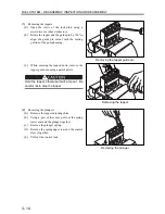
(b)
When the tester handle is pumped at a rate of
approx. one cycle per second, fuel should be
sprayed in a fairly straight pattern.
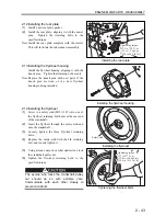
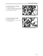
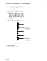
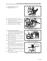
(3)
Clean or replace when spraying badly
(a)
Loosen the nozzle retaining nut to remove the
nozzle tip assembly. Clean the needle valve
and the nozzle tip body.
When removing the nozzle tip assembly, never
tap on the end of the assembly.
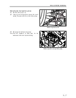
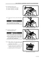
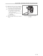
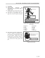
(b)
Wash the needle valve and the nozzle tip body
in clean wash oil. Reassemble them in clean
light oil.
Note: The needle valve and the nozzle tip body are
precision machined parts. Handle with care and
never change their combination.
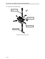
Replacing the fuel injection nozzle tip
assembly
Nozzle tip end
Fuel spray patterns
Cleaning the fuel injection nozzle tip
components
Needle
valve
Nozzle tip
body
Good
Bad
(Diffused)
Bad
(Dribbling)
Bad
(Feathering)
Bad
(Deflected)
Summary of Contents for diesel engines
Page 5: ......
Page 33: ...SERVICE STANDARDS 1 20 ...
Page 34: ...1 General Tools 1 22 2 Special Tools 1 23 TOOLS LIST ...
Page 37: ...TOOLS LIST 1 24 ...
Page 41: ...OVERHAUL TIMING 1 28 ...
Page 46: ......
Page 47: ......
Page 61: ...ENGINE MAIN PARTS DISASSEMBLY 2 16 ...
Page 99: ...FUEL SYSTEM REMOVAL 3 8 ...
Page 115: ...FUEL SYSTEM DISASSEMBLY INSPECTION AND REASSEMBLY 3 24 ...
Page 119: ...FUEL SYSTEM INSTALLATION 3 28 2 Governor Installing the governor Installation sequence ...
Page 123: ...FUEL SYSTEM INSTALLATION 3 32 ...
Page 131: ...OIL SYSTEM DISASSEMBLY INSPECTION AND REASSEMBLY 4 8 ...
Page 143: ...COOLING SYSTEM DISASSEMBLY INSPECTION AND REASSEMBLY 5 8 ...
Page 150: ......
Page 151: ......
Page 153: ...INLET AND EXHAUST SYSTEMS REMOVAL 6 4 ...
Page 159: ...INLET AND EXHAUST SYSTEMS INSTALLATION 6 10 ...
Page 160: ...1 Starter 7 2 2 Alternator 7 3 3 Stop Solenoid 7 4 4 Glow Plug 7 5 ELECTRICAL SYSTEM REMOVAL ...
Page 165: ...ELECTRICAL SYSTEM REMOVAL 7 6 ...
Page 189: ...ELECTRICAL SYSTEM INSTALLATION 7 30 ...
Page 207: ...MISCELLANEOUS 9 4 ...