


294
Consumables/Maintenance Parts/Options
Purchase these consumables, maintenance parts, and options from the dealer where
you bought the machine.
·
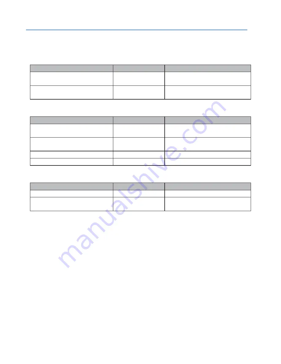
Consumables
Product Name
Model
Description
Toner Cartridge
Enables printing of approximately
5,000 pages.
Image Drum Unit
Enables printing of approximately
25,000 pages.
·
Maintenance Parts
Product Name
Model
Description
Fuser Unit
Enables printing of approximately
100,000 pages.
Transfer Belt Unit
Enables printing of approximately
100,000 pages.
Paper Feed Roller
Enables printing of approximately 60 km.
Feed Roller
Enables printing of approximately 60 km.
·
Options
Product Name
Model
Description
Wireless LAN Module
Enables wireless connections.
Presenter Unit
The Presenter Unit is installed to stop the
printed paper before it is fully ejected.
·
The print quality deteriorates after one year or more passes since you open the toner cartridge
and image drum unit. In this case, prepare a new consumable for replacement.
·
Do not open the package until the consumable is ready for use.
·
Avoid direct sunlight and store it in a location in the range of 0 to 35°C temperature and 20 to 85%
relative humidity.
·
Do not store it in a location subject to high or rapid changes in temperatures or humidity.
·
Keep it away from children.
Summary of Contents for 360C
Page 1: ...360C Operator s Manual 880076 0101 Rev 2 ...
Page 17: ...17 Unpacking How to Unpack the Machine Checking the Accessories Installing Consumables 2 ...
Page 24: ...24 ...
Page 36: ...35 7 Tighten the screws x 2 8 Connect the connector ...
Page 37: ...36 9 Attach the Cover Cable PSNT 10 Attach the Cap Cover PSNT x 2 ...
Page 50: ...49 ...
Page 91: ...90 ...
Page 147: ...146 ...
Page 156: ...155 8 Remove the cover toner 9 Close the top cover 10 Open the toner cartridge cover ...
Page 167: ...166 8 Close the top cover ...
Page 178: ...177 15 Close the feeder cover until it clicks ...
Page 179: ...178 ...
Page 198: ...197 4 Close the feeder cover until it clicks ...
Page 233: ...232 ...
Page 244: ...243 The settings of the machine can be changed from the Admin Setup tab ...
Page 280: ...279 11 Confirm the setting results and click Back ...
Page 289: ...288 ...
Page 296: ......
Page 297: ......


