26
A
B
a
m
l
1
2
2.5mm
2
2.5mm
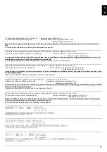
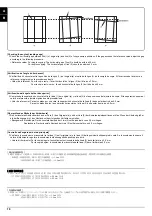
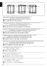
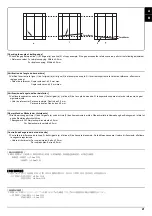
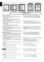
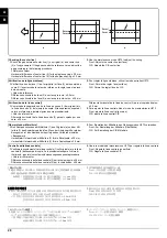
[Checking the leading edge timing]
1.
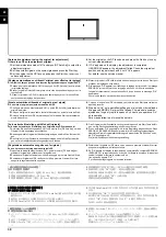
Check the gap between line (1) on original (a) and line (2) of copy
example. If the gap exceeds the reference value, adjust the gap
according to the following procedure.
<Reference value>
Vertical gap of line (2): within ±2.5 mm
2.
Use the maintenance mode U071 to adjust the timing.
Front Head: Adjusts the leading edge timing (surface)
Front Tail: Adjusts the trailing edge timing (surface)
CIS Head: Adjusts the leading edge timing for CIS scanning.
CIS Tail: Adjusts the trailing edge timing for CIS scanning.
[Vérification de la synchronisation du bord avant]
1.
Vérifier l’écart entre la ligne (1) de l’original (a) et la ligne (2) de l’exem-
ple de copie. Si l’écart excède la valeur de référence, le régler selon la
procédure suivante.
<Valeur de référence>
Écart vertical de la ligne (2) : ±2,5 mm
2.
Pour régler la synchronisation, utilisez le mode entretien U071.
Front Head: Permet de régler la synchronisation du bord de tête (surface)
Front Tail: Permet de régler la synchronisation du bord arrière (surface)
CIS Head: Permet de régler la synchronisation du bord de tête pour le balayage par le CIS.
CIS Tail: Permet de régler la synchronisation du bord arrière pour le balayage par le CIS.
[Cambio de la sincronización de borde superior]
1.
Compruebe la separación entre la línea (1) del original (a) y la línea (2)
del ejemplo de copia. Si la separación supera el valor de referencia,
ajústela siguiendo este procedimiento.
<Valor de referencia>
Separación vertical de la línea (2): dentro de ±2,5 mm
2.
Para ajustar la sincronización utilice el modo de mantenimiento U071.
Front Head: Ajusta la sincronización del borde superior (anverso).
Front Tail: Ajusta la sincronización del borde inferior (anverso).
CIS Head: Ajusta la sincronización del borde superior para exploración CIS.
CIS Tail: Ajusta la sincronización del borde inferior para exploración CIS.
[Überprüfen des Vorderkanten-Timings]
1.
Den Abstand zwischen der Linie (1) des Originals (a) und der Linie (2)
des Kopierbeispiels prüfen. Wenn der Abstand größer als der
Bezugswert ist, den Abstand mit dem folgenden Verfahren einstellen.
<Bezugswert>
Vertikaler Abstand der Linie (2): Innerhalb ±2,5 mm
2.
Zum Einstellen des Timing den Wartungsmodus U071 verwenden.
Front Head: Zur Einstellung des Vorderkanten-Timing (Oberfläche)
Front Tail: Zur Einstellung des Hinterkanten-Timing (Oberfläche)
CIS Head: Zur Einstellung des Vorderkanten-Timing für CIS-Scannen.
CIS Tail: Zur Einstellung des Hinterkanten-Timing für CIS-Scannen.
[Controllo della sincronizzazione del bordo principale]
1.
Verificare lo scostamento fra la linea (1) sull’originale (a) e la linea (2)
dell’esempio di copia. Se lo scostamento supera il valore di riferimento,
regolare lo scostamento stesso seguendo questa procedura.
<Valore di riferimento>
Scostamento verticale della linea (2) compreso fra ±2,5 mm
2.
Usare la modalità di manutenzione U071 per regolare la
sincronizzazione.
Front Head: Regola la sincronizzazione del bordo principale (superficie)
Front Tail: Regola la sincronizzazione del bordo di uscita (superficie)
CIS Head: Regola la sincronizzazione del bordo principale per scansione CIS.
CIS Tail: Regola la sincronizzazione del bordo di uscita per scansione CIS.
[ 先端タイミング確認 ]
1.
原稿 (a) の線 (1) とコピーサンプルの線 (2) のずれを確認する。ずれ
が基準値外の場合、
次の手順で調整を行う。
<基準値>
線 (2) の上下ずれ:±2.5mm 以内
2.
メンテナンスモード U071 をセットし、
調整を行う。
Front Head :先端タイミング ( 表面 ) を調整する
Front Tail :後端タイミング ( 表面 ) を調整する
CIS Head: CIS 読み込み時の先端タイミングを調整する
CIS Tail: CIS 読み込み時の後端タイミングを調整する
[ 确认前端定时调整 ]
1.
确认原稿(a)上的线(1)和复印样本上的线(2)之间的偏移值。如果偏
移值超过标准值,则按照下列步骤进行调整。
< 标准值 >
线(2)的上下偏移值 :±2.5mm 以内
2.
使用维修模式 U071 调整定时。
Front Head :调整前端定时 ( 正面 )
Front Tail :调整后端定时 ( 正面 )
CIS Head :调整 CIS 读取时的前段对位
CIS Tail :调整 CIS 读取时的后端定时
[ 선단 타이밍확인 ]
1.
원고 (a) 선 (1) 과 샘플 카피 선 (2) 의 차이를 확인합니다 . 차이가 기준
치 외의 경우 다음 순서로 조정을 합니다 .
<기준치>
선 (2) 의 상하차이:±2.5mm 이내
2.
메인터넌스 모드 U071 을 세트하고 조정을 합니다 .
Front Head :선단 타이밍 ( 표면 ) 을 조정합니다 .
Front Tail :후단 타이밍 ( 표면 ) 을 조정합니다 .
CIS Head: CIS 스캔 시의 선단 타이밍을 조정합니다 .
CIS Tail: CIS 스캔 시의 후단 타이밍을 조정합니다 .
A
B
Summary of Contents for Copystar CS 3011i
Page 1: ...SERVICE MANUAL Published in September 2016 2RHSM 1 Rev 1 6 3011i 6 3511i ...
Page 4: ...This page is intentionally left blank ...
Page 10: ...This page is intentionally left blank ...
Page 78: ...2RG 2RH 1 2 51 B B A A B B A A B B A A Tray lower cover Pin Pin ...
Page 83: ...2RG 2RH 1 2 56 This page is intentionally left blank ...
Page 504: ...2RG 2RH 2 2 8 This page is intentionally left blank ...
Page 568: ...Installation Guide DP 7100 Document processor Installation Guide ...
Page 572: ...2 1mm 0mm ն ո պ ջ չ շ A D C B B A ...
Page 573: ...3 ռ ս վ ր ւ ց տ E A ...
Page 574: ...4 ք द I M3x8 փ F G M4x10 K J H A ...
Page 575: ...5 ON ध A ...
Page 577: ...7 շ յ ն ո D E B ...
Page 578: ...8 չ պ F G M4x10 H I M3x8 K J ջ B ...
Page 579: ...9 ռ B ...
Page 589: ...19 ո ն շ պ ջ չ 8 6 7 10 11 9 A B ...
Page 599: ...DP 7110 Document processor Installation Guide ...
Page 603: ...2 շ շ 2 շ 2 շ C M4x14 E ߑ ߒ ߓ ߔ ո շ 2 ߑ ն A ...
Page 604: ...3 ߘ ո ߕ ߗ ո չ պ ջ ߖ F G H M3x8 BLACK A ...
Page 605: ...4 ռ վ ր ւ ց ࠉտ ս I A ...
Page 606: ...5 J L փ ք द K M3x8 K M3x8 K M3x8 ध A ...
Page 607: ...6 ऩ प भ फ ब न म O N A ...
Page 608: ...7 ON य A ...
Page 610: ...9 շ ո շ 2 շ 2 շ 2 ߑ ն շ ߑ ߒ ߓ ߔ C M4x14 E B ...
Page 611: ...10 ߖ ߕ ߘ ߎ չ պ ջ ߗ F G ո H M3x8 BLACK B ...
Page 612: ...11 ռ ս տ ր ց վ I B ...
Page 613: ...12 ւ ք द ध न փ J L P K M3x8 K M3x8 B ...
Page 614: ...13 ऩ प फ O N B ...
Page 634: ...DP 7120 Document processor Installation Guide ...
Page 638: ...2 1mm 0mm ն շ ո չ ջ պ B B A D C A ...
Page 639: ...3 ռ ս վ տ ց ր E A ...
Page 640: ...4 G ւ F F ք փ H ON 10 mm 10 mm A ...
Page 642: ...6 շ ո յ ն D B ...
Page 643: ...7 չ E B ...
Page 644: ...8 F ON G պ F ջ ռ H 10 mm 10 mm B ...
Page 653: ...17 ղ ն շ ճ մ յ 2 6 7 3 4 5 A B ...
Page 655: ...19 չ ջ պ ս վ ռ 9 11 10 13 14 12 10 mm A B ...
Page 665: ...PF 791 500 x 2 Paper feeder Installation Guide ...
Page 673: ...PF 810 3000 sheet deck Installation Guide ...
Page 686: ...DF 791 3000 sheet finisher Installation Guide ...
Page 701: ...DF 7120 1000 sheet finisher Installation Guide ...
Page 705: ...2 մ յ ն 7 7 15 a b a a b b b a A ...
Page 706: ...3 ո շ չ պ A ...
Page 707: ...4 ջ ռ ս c d 14 c d c d 12 c d ջ ռ ս c d 14 c d c d 12 c d A ...
Page 708: ...5 վ ր D ց ON տ A ...
Page 710: ...7 L յ մ ն շ B ...
Page 712: ...9 ս ռ վ տ G B ...
Page 713: ...10 ր ց ւ b a 17 17 25 a b a a b b B ...
Page 714: ...11 ք փ द c d 24 c d c d 22 c d B ...
Page 715: ...12 न ध ऩ प B ...
Page 716: ...13 ब फ ON D B ...
Page 719: ...AK 740 Bridge unit Installation Guide ...
Page 721: ...MT 730 Mailbox Installation Guide ...
Page 736: ...PH 7A C D Punch unit Installation Guide ...
Page 757: ...DT 730 B Document tray Installation Guide ...
Page 759: ...5 2013 5 302LC56750 01 H F G D D 6 4 3 7 E C D D M4 8 M4 8 M4 8 M4 8 ...
Page 760: ...FAX System 12 Installation Guide ...


