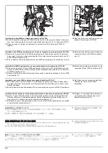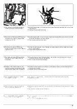
9
M
K
26
27
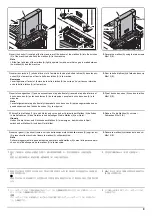
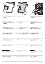
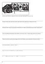
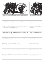
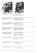
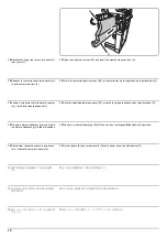
15.
Plug the 2 punch PWB wires into the con-
nectors (27) on the DF main PWB (26).
16.
Install the small clamp (K) on the finisher, then pass and fasten the wires from the motor unit and
hole punch unit.
17.
Attach the ferrite core (M) to the wire.
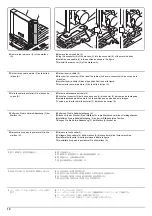
15.
Raccorder les 2 câbles de la PWB de la per-
foratrice aux connecteurs (27) de la PWB
principale du DF (26).
16.
Monter le petit collier (K) sur le retoucheur puis faire passer les câbles du moteur et de la perfora-
trice dans ce collier pour les fixer en place
17.
Fixer le noyau en ferrite (M) au câble.
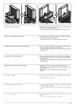
15.
Enchufe los 2 cables del PWB de per-
foración a los conectores (27) del PWB prin-
cipal del DF (26).
16.
Instale el sujetador pequeño (K) en el finalizador, después tienda y ajuste los cables de la unidad
motriz y la perforadora.
17.
Fije el núcleo de ferrita (M) al cable.
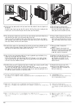
15.
Die 2 Kabel der Locher-PWB an die Steck-
verbinder (27) der DF-Haupt-PWB (26)
anschließen.
16.
Die kleine Klemme (K) am Finisher anbringen, dann die Kabel von der Motoreinheit und der
Lochereinheit hindurchführen und befestigen.
17.
Den Ferritkern (M) am Kabel befestigen.
15.
Collegare i 2 cavi della scheda a circuiti
stampati di perforazione nei connettori (27)
sulla scheda principale PWB (26) della DF.
16.
Installare il morsetto piccolo (K) sul finitore, e quindi passare e fissare i cavi dall’unità motore e
dall’unità di perforazione.
17.
Applicare il nucleo in ferrite (M) al cavo.
15.
パンチ基板の電線 2 本を DF 主回路基板
(26) のコネクター(27) に接続する。
16.
クランプ小(K)をフィニッシャーに取り付け、モーターユニットとパンチユニットからの電線を
通し、
固定する。
17.
フェライトコア(M)
を電線に取り付ける。
15.
将打孔电路板的 2 根电线与 DF 主电路板
(26) 的接插件 (27) 连接。
16.
把小固定夹(K)安装在装订器上,从电机单元和打孔单元出来的导线穿过固定夹来固定。
17.
用磁环(M)套住导线。
15.
펀치기판의 전선 2 선을 DF 주 회로기판
(26) 의 커넥터 (27) 에 접속합니다 .
16.
클램프 소(K)를 피니셔에 장착 , 모터 유니트와 펀치 유니트에서부터 전선을 통과시키고 고정합
니다 .
17.
페라이트 코어(M)를 전선으로 장착합니다 .
Summary of Contents for Copystar CS 3011i
Page 1: ...SERVICE MANUAL Published in September 2016 2RHSM 1 Rev 1 6 3011i 6 3511i ...
Page 4: ...This page is intentionally left blank ...
Page 10: ...This page is intentionally left blank ...
Page 78: ...2RG 2RH 1 2 51 B B A A B B A A B B A A Tray lower cover Pin Pin ...
Page 83: ...2RG 2RH 1 2 56 This page is intentionally left blank ...
Page 504: ...2RG 2RH 2 2 8 This page is intentionally left blank ...
Page 568: ...Installation Guide DP 7100 Document processor Installation Guide ...
Page 572: ...2 1mm 0mm ն ո պ ջ չ շ A D C B B A ...
Page 573: ...3 ռ ս վ ր ւ ց տ E A ...
Page 574: ...4 ք द I M3x8 փ F G M4x10 K J H A ...
Page 575: ...5 ON ध A ...
Page 577: ...7 շ յ ն ո D E B ...
Page 578: ...8 չ պ F G M4x10 H I M3x8 K J ջ B ...
Page 579: ...9 ռ B ...
Page 589: ...19 ո ն շ պ ջ չ 8 6 7 10 11 9 A B ...
Page 599: ...DP 7110 Document processor Installation Guide ...
Page 603: ...2 շ շ 2 շ 2 շ C M4x14 E ߑ ߒ ߓ ߔ ո շ 2 ߑ ն A ...
Page 604: ...3 ߘ ո ߕ ߗ ո չ պ ջ ߖ F G H M3x8 BLACK A ...
Page 605: ...4 ռ վ ր ւ ց ࠉտ ս I A ...
Page 606: ...5 J L փ ք द K M3x8 K M3x8 K M3x8 ध A ...
Page 607: ...6 ऩ प भ फ ब न म O N A ...
Page 608: ...7 ON य A ...
Page 610: ...9 շ ո շ 2 շ 2 շ 2 ߑ ն շ ߑ ߒ ߓ ߔ C M4x14 E B ...
Page 611: ...10 ߖ ߕ ߘ ߎ չ պ ջ ߗ F G ո H M3x8 BLACK B ...
Page 612: ...11 ռ ս տ ր ց վ I B ...
Page 613: ...12 ւ ք द ध न փ J L P K M3x8 K M3x8 B ...
Page 614: ...13 ऩ प फ O N B ...
Page 634: ...DP 7120 Document processor Installation Guide ...
Page 638: ...2 1mm 0mm ն շ ո չ ջ պ B B A D C A ...
Page 639: ...3 ռ ս վ տ ց ր E A ...
Page 640: ...4 G ւ F F ք փ H ON 10 mm 10 mm A ...
Page 642: ...6 շ ո յ ն D B ...
Page 643: ...7 չ E B ...
Page 644: ...8 F ON G պ F ջ ռ H 10 mm 10 mm B ...
Page 653: ...17 ղ ն շ ճ մ յ 2 6 7 3 4 5 A B ...
Page 655: ...19 չ ջ պ ս վ ռ 9 11 10 13 14 12 10 mm A B ...
Page 665: ...PF 791 500 x 2 Paper feeder Installation Guide ...
Page 673: ...PF 810 3000 sheet deck Installation Guide ...
Page 686: ...DF 791 3000 sheet finisher Installation Guide ...
Page 701: ...DF 7120 1000 sheet finisher Installation Guide ...
Page 705: ...2 մ յ ն 7 7 15 a b a a b b b a A ...
Page 706: ...3 ո շ չ պ A ...
Page 707: ...4 ջ ռ ս c d 14 c d c d 12 c d ջ ռ ս c d 14 c d c d 12 c d A ...
Page 708: ...5 վ ր D ց ON տ A ...
Page 710: ...7 L յ մ ն շ B ...
Page 712: ...9 ս ռ վ տ G B ...
Page 713: ...10 ր ց ւ b a 17 17 25 a b a a b b B ...
Page 714: ...11 ք փ द c d 24 c d c d 22 c d B ...
Page 715: ...12 न ध ऩ प B ...
Page 716: ...13 ब फ ON D B ...
Page 719: ...AK 740 Bridge unit Installation Guide ...
Page 721: ...MT 730 Mailbox Installation Guide ...
Page 736: ...PH 7A C D Punch unit Installation Guide ...
Page 757: ...DT 730 B Document tray Installation Guide ...
Page 759: ...5 2013 5 302LC56750 01 H F G D D 6 4 3 7 E C D D M4 8 M4 8 M4 8 M4 8 ...
Page 760: ...FAX System 12 Installation Guide ...

