


4
3.
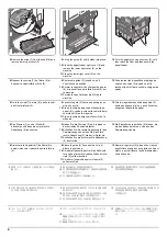
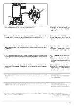
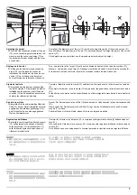
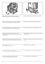
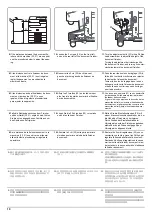
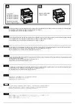
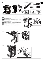
Remove the machine interface cover (3).
4.
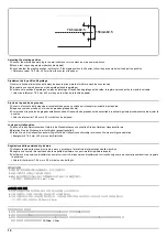
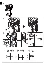
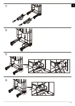
Attach the connecting plate (C) to the machine using 2 M4 × 20 screws (G). Attach them at the
point as shown above.
Only If PF-810 is installed, execute step 5
5.
Remove the breakaway cover (4) from the left cover.
If PF-791 is installed, proceed to step 6.
3.
Déposer le couvercle d'interface (3) de la
machine.
4.
Fixez la plaque de connexion (C) à la machine à l'aide de 2 vis M4 × 20 (G).Raccordez-les au
point indiqué ci-dessus.
N'exécutez l'étape 5 que si le PF-810 est installé.
5.
Déposer le couvercle amovible (4) du couvercle gauche.
Si le PF-791 est installé, passez à l'étape 6.
3.
Quite la cubierta de la interfaz (3) de la
máquina.
4.
Fije la placa de conexión (C) a la máquina mediante 2 tornillos M4 × 20 (G).Conéctelas en el
punto que se muestra arriba.
Solo si está instalado PF-810, ejecute el paso 5.
5.
Quite la cubierta divisoria (4) de la cubierta izquierda.
Si está instalado PF-791, vaya al paso 6.
3.
Nehmen Sie die Schnittstellenabdeckung (3)
des Geräts ab.
4.
Bringen Sie die Verbindungsplatte (C) mit 2 M4 × 20 Schrauben (G) am Gerät an.Bringen Sie
diese an der in der Abbildung gezeigten Stelle an.
Nur wenn der PF-810 installiert ist, führen Sie Schritt 5 aus.
5.
Nehmen Sie die Ablösungsabdeckung (4) von der linken Abdeckung ab.
Falls PF-791 installiert ist, führen Sie Schritt 6 aus.
3.
Rimuovere la copertura di interfaccia (3)
della macchina.
4.
Applicare la piastra di connessione (C) alla macchina utilizzando le 2 viti M4 × 20 (G).Fissare
nella posizione sopra indicata.
Se è installato solo l'alimentatore carta modello PF-810, eseguire il punto 5.
5.
Rimuovere il coperchio di distacco (4) dal coperchio sinistro.
Se è installato solo l'alimentatore carta modello PF-791, proseguire con il punto 6.
3.
機械本体のインターフェイスカバー(3) を
取り外す。
4.
連結板 (C) をビス M4×20(G)2 本で、
機械本体に取り付ける。
図の位置で取り付けること。
PF‑810 が装着されている場合のみ手順 5 を行う。
5.
左カバーの割りカバー部 (4) を切り取る。
PF‑791 が装着されている場合は手順 6 に進む。
3.
拆下机器的接口盖板 (3)。
4.
使用 2 颗 M4×20(G) 螺丝将连接板 (C) 安装到机器上。按图示位置来安装。
仅安装了 PF-810 的情况时,执行步骤 5。
5.
去除左侧盖板上的可去除部 (4)。
当安装了 PF-791 的情况时,进入步骤 6。
3.
본체의 인터페이스 커버 (3) 를 제거합니다 .
4.
나사 M4 × 20(G) 2 개를 사용하여 연결판 (C) 을 본체에 부착합니다 . 위에 표시된 위치에 부착
합니다 . 위에 표시된 위치에 부착합니다 .
PF-810 만 설치되어 있는 경우 스텝 5 를 실행하십시오 .
5.
좌측커버의 분할커버부 (4) 를 떼어 냅니다 .
PF-791 이 설치되어 있는 경우 스텝 6 을 진행하십시오 .
3
C
4
G(M4x20)
G(M4x20)
Summary of Contents for Copystar CS 3011i
Page 1: ...SERVICE MANUAL Published in September 2016 2RHSM 1 Rev 1 6 3011i 6 3511i ...
Page 4: ...This page is intentionally left blank ...
Page 10: ...This page is intentionally left blank ...
Page 78: ...2RG 2RH 1 2 51 B B A A B B A A B B A A Tray lower cover Pin Pin ...
Page 83: ...2RG 2RH 1 2 56 This page is intentionally left blank ...
Page 504: ...2RG 2RH 2 2 8 This page is intentionally left blank ...
Page 568: ...Installation Guide DP 7100 Document processor Installation Guide ...
Page 572: ...2 1mm 0mm ն ո պ ջ չ շ A D C B B A ...
Page 573: ...3 ռ ս վ ր ւ ց տ E A ...
Page 574: ...4 ք द I M3x8 փ F G M4x10 K J H A ...
Page 575: ...5 ON ध A ...
Page 577: ...7 շ յ ն ո D E B ...
Page 578: ...8 չ պ F G M4x10 H I M3x8 K J ջ B ...
Page 579: ...9 ռ B ...
Page 589: ...19 ո ն շ պ ջ չ 8 6 7 10 11 9 A B ...
Page 599: ...DP 7110 Document processor Installation Guide ...
Page 603: ...2 շ շ 2 շ 2 շ C M4x14 E ߑ ߒ ߓ ߔ ո շ 2 ߑ ն A ...
Page 604: ...3 ߘ ո ߕ ߗ ո չ պ ջ ߖ F G H M3x8 BLACK A ...
Page 605: ...4 ռ վ ր ւ ց ࠉտ ս I A ...
Page 606: ...5 J L փ ք द K M3x8 K M3x8 K M3x8 ध A ...
Page 607: ...6 ऩ प भ फ ब न म O N A ...
Page 608: ...7 ON य A ...
Page 610: ...9 շ ո շ 2 շ 2 շ 2 ߑ ն շ ߑ ߒ ߓ ߔ C M4x14 E B ...
Page 611: ...10 ߖ ߕ ߘ ߎ չ պ ջ ߗ F G ո H M3x8 BLACK B ...
Page 612: ...11 ռ ս տ ր ց վ I B ...
Page 613: ...12 ւ ք द ध न փ J L P K M3x8 K M3x8 B ...
Page 614: ...13 ऩ प फ O N B ...
Page 634: ...DP 7120 Document processor Installation Guide ...
Page 638: ...2 1mm 0mm ն շ ո չ ջ պ B B A D C A ...
Page 639: ...3 ռ ս վ տ ց ր E A ...
Page 640: ...4 G ւ F F ք փ H ON 10 mm 10 mm A ...
Page 642: ...6 շ ո յ ն D B ...
Page 643: ...7 չ E B ...
Page 644: ...8 F ON G պ F ջ ռ H 10 mm 10 mm B ...
Page 653: ...17 ղ ն շ ճ մ յ 2 6 7 3 4 5 A B ...
Page 655: ...19 չ ջ պ ս վ ռ 9 11 10 13 14 12 10 mm A B ...
Page 665: ...PF 791 500 x 2 Paper feeder Installation Guide ...
Page 673: ...PF 810 3000 sheet deck Installation Guide ...
Page 686: ...DF 791 3000 sheet finisher Installation Guide ...
Page 701: ...DF 7120 1000 sheet finisher Installation Guide ...
Page 705: ...2 մ յ ն 7 7 15 a b a a b b b a A ...
Page 706: ...3 ո շ չ պ A ...
Page 707: ...4 ջ ռ ս c d 14 c d c d 12 c d ջ ռ ս c d 14 c d c d 12 c d A ...
Page 708: ...5 վ ր D ց ON տ A ...
Page 710: ...7 L յ մ ն շ B ...
Page 712: ...9 ս ռ վ տ G B ...
Page 713: ...10 ր ց ւ b a 17 17 25 a b a a b b B ...
Page 714: ...11 ք փ द c d 24 c d c d 22 c d B ...
Page 715: ...12 न ध ऩ प B ...
Page 716: ...13 ब फ ON D B ...
Page 719: ...AK 740 Bridge unit Installation Guide ...
Page 721: ...MT 730 Mailbox Installation Guide ...
Page 736: ...PH 7A C D Punch unit Installation Guide ...
Page 757: ...DT 730 B Document tray Installation Guide ...
Page 759: ...5 2013 5 302LC56750 01 H F G D D 6 4 3 7 E C D D M4 8 M4 8 M4 8 M4 8 ...
Page 760: ...FAX System 12 Installation Guide ...


