18
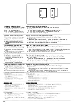
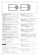
Centering the hole punch position
1.
Enter the maintenance mode U246, select Finisher and Punch Width.
2.
Adjust the values.
If the punch hole is too close to the front of the machine: Decrease the
setting value.
If the punch hole is too close to the rear of the machine: Increase the
setting value.
3.
Press the Start key to confirm the setting value.
<Reference value>
Metric specification: d = 80 mm ± 0.5, e = 40 mm ± 2
Inch specification: d = 2.75 inch ± 0.5, e = 1.375 inch ± 2,
f = 4.25 inch ± 0.5
Centrage de la position de perforation
1.
Passer en mode maintenance U246, sélectionner Finisher et Punch Width.
2.
Régler les valeurs.
Si la perforation est trop proche de l'avant de la machine: Diminuez la valeur de
réglage.
Si la perforation est trop proche de l'arrière de la machine: Augmentez la valeur
de réglage.
3.
Appuyer sur la touche de Start pour confirmer la valeur de réglage.
<Valeur de référence>
Spécifications métriques: d = 80 mm ± 0,5, e = 40 mm ± 2
Spécifications en pouces: d = 2,75 pouces ± 0,5, e = 1,375 pouces ± 2,
f = 4.25 pouces ± 0,5
Centrado de la posición de perforación
1.
Entre en el modo de mantenimiento U246, seleccione Finisher y Punch Width.
2.
Ajuste los valores.
Si la perforación se encuentra demasiado cerca del frente de la máquina:
Reduzca el valor de configuración.
Si la perforación se encuentra demasiado cerca de la parte trasera de la
máquina: Aumente el valor de configuración.
3.
Pulse la tecla de Start para confirmar el valor de configuración.
<Valor de referencia>
Sistema métrico: d = 80 mm ± 0,5, e = 40 mm ± 2
En pulgadas: d = 2,75 pulgada ± 0,5, e = 1,375 pulgada ± 2,
f = 4.25 ± 0,5 pulgada
Zentrieren der Stanzlochposition
1.
Schalten Sie in den Wartungsmodus U246, wählen Sie Finisher und Punch
Width.
2.
Die Werte einstellen.
Falls die Lochung zu nah an der Gerätefront liegt: Den Einstellwert verringern.
Falls die Lochung zu weit weg von der Gerätefront liegt: Den Einstellwert
erhöhen.
3.
Den Einstellwert durch Drücken der Start-Taste bestätigen.
<Bezugswert>
Metrischer Abstand: d = 80 mm ± 0,5; e = 40 mm ± 2
Abstand in Zoll: d = 2,75 Zoll ± 0,5, e = 1,375 Zoll ± 2,
f = 4.25 Zoll ± 0,5
Centratura della posizione dei fori di perforazione
1.
Entrare in modalità manutenzione U246, selezionare Finisher e Punch Width.
2.
Regolare i valori.
Se la posizione dei fori di perforazione è troppo vicina alla parte anteriore della
macchina: Diminuire il valore dell'impostazione.
Se la posizione dei fori di perforazione è troppo vicina alla parte posteriore della
macchina: Aumentare il valore dell'impostazione.
3.
Premere il tasto di Start per confermare il valore dell'impostazione.
<Valore di riferimento>
Specificazione in unità metrica: d = 80 mm ± 0,5, e = 40 mm ± 2
Specificazione in pollici: d = 2,75 pollici ± 0.5, e = 1,375 pollici ± 2,
f = 4.25 pollici ± 0.5
パンチ位置センター調整
1.
メンテナンスモード U246 をセットし、Finisher、
Punch Width を選択す
る。
2.
設定値を調整する。
パンチ穴の位置が機械前側にずれている場合:設定値を下げる。
パンチ穴の位置が機械後側にずれている場合:設定値を上げる。
3.
スタートキーを押し、
設定値を確定する。
<基準値>
センチ仕様:d=80mm±0.5、e=40mm±2
インチ仕様:d=2.75inch±0.5、
e=1.375inch±2、f=4.25inch±0.5
打孔位置中心调节
1.
设置维护模式 U246,选择 Finisher、Punch Width。
2.
调整设定值。
打孔位置向机器前部偏移时:调低设定值。
打孔位置向机器后部偏移时:调高设定值。
3.
按 Start 键,以确定设定值。
<基准值>
公制规格 :d=80mm±0.5、e=40mm±2
英制规格 :d=2.75inch±0.5、e=1.375inch±2、f=4.25inch±0.5
펀치위치 센터조정
1.
메인터넌스 모드 U246 를 세트하고 Finisher, Punch Width 를 선택합
니다 .
2.
설정치를 조정합니다 .
펀치구멍이 기기 앞측으로 벗어난 경우:설정치를 내립니다 .
펀치구멍의 위치가 기기 뒷측으로 벗어난 경우:설정치를 높입니다 .
3.
시작키를 누르고 설정치를 확인합니다 .
<기준치>
센치 사양:d=80mm±0.5, e=40mm±2
인치사양:d=2.75inch±0.5, e=1.375inch±2, f=4.25inch±0.5
d
e
f
f
Summary of Contents for Copystar CS 3011i
Page 1: ...SERVICE MANUAL Published in September 2016 2RHSM 1 Rev 1 6 3011i 6 3511i ...
Page 4: ...This page is intentionally left blank ...
Page 10: ...This page is intentionally left blank ...
Page 78: ...2RG 2RH 1 2 51 B B A A B B A A B B A A Tray lower cover Pin Pin ...
Page 83: ...2RG 2RH 1 2 56 This page is intentionally left blank ...
Page 504: ...2RG 2RH 2 2 8 This page is intentionally left blank ...
Page 568: ...Installation Guide DP 7100 Document processor Installation Guide ...
Page 572: ...2 1mm 0mm ն ո պ ջ չ շ A D C B B A ...
Page 573: ...3 ռ ս վ ր ւ ց տ E A ...
Page 574: ...4 ք द I M3x8 փ F G M4x10 K J H A ...
Page 575: ...5 ON ध A ...
Page 577: ...7 շ յ ն ո D E B ...
Page 578: ...8 չ պ F G M4x10 H I M3x8 K J ջ B ...
Page 579: ...9 ռ B ...
Page 589: ...19 ո ն շ պ ջ չ 8 6 7 10 11 9 A B ...
Page 599: ...DP 7110 Document processor Installation Guide ...
Page 603: ...2 շ շ 2 շ 2 շ C M4x14 E ߑ ߒ ߓ ߔ ո շ 2 ߑ ն A ...
Page 604: ...3 ߘ ո ߕ ߗ ո չ պ ջ ߖ F G H M3x8 BLACK A ...
Page 605: ...4 ռ վ ր ւ ց ࠉտ ս I A ...
Page 606: ...5 J L փ ք द K M3x8 K M3x8 K M3x8 ध A ...
Page 607: ...6 ऩ प भ फ ब न म O N A ...
Page 608: ...7 ON य A ...
Page 610: ...9 շ ո շ 2 շ 2 շ 2 ߑ ն շ ߑ ߒ ߓ ߔ C M4x14 E B ...
Page 611: ...10 ߖ ߕ ߘ ߎ չ պ ջ ߗ F G ո H M3x8 BLACK B ...
Page 612: ...11 ռ ս տ ր ց վ I B ...
Page 613: ...12 ւ ք द ध न փ J L P K M3x8 K M3x8 B ...
Page 614: ...13 ऩ प फ O N B ...
Page 634: ...DP 7120 Document processor Installation Guide ...
Page 638: ...2 1mm 0mm ն շ ո չ ջ պ B B A D C A ...
Page 639: ...3 ռ ս վ տ ց ր E A ...
Page 640: ...4 G ւ F F ք փ H ON 10 mm 10 mm A ...
Page 642: ...6 շ ո յ ն D B ...
Page 643: ...7 չ E B ...
Page 644: ...8 F ON G պ F ջ ռ H 10 mm 10 mm B ...
Page 653: ...17 ղ ն շ ճ մ յ 2 6 7 3 4 5 A B ...
Page 655: ...19 չ ջ պ ս վ ռ 9 11 10 13 14 12 10 mm A B ...
Page 665: ...PF 791 500 x 2 Paper feeder Installation Guide ...
Page 673: ...PF 810 3000 sheet deck Installation Guide ...
Page 686: ...DF 791 3000 sheet finisher Installation Guide ...
Page 701: ...DF 7120 1000 sheet finisher Installation Guide ...
Page 705: ...2 մ յ ն 7 7 15 a b a a b b b a A ...
Page 706: ...3 ո շ չ պ A ...
Page 707: ...4 ջ ռ ս c d 14 c d c d 12 c d ջ ռ ս c d 14 c d c d 12 c d A ...
Page 708: ...5 վ ր D ց ON տ A ...
Page 710: ...7 L յ մ ն շ B ...
Page 712: ...9 ս ռ վ տ G B ...
Page 713: ...10 ր ց ւ b a 17 17 25 a b a a b b B ...
Page 714: ...11 ք փ द c d 24 c d c d 22 c d B ...
Page 715: ...12 न ध ऩ प B ...
Page 716: ...13 ब फ ON D B ...
Page 719: ...AK 740 Bridge unit Installation Guide ...
Page 721: ...MT 730 Mailbox Installation Guide ...
Page 736: ...PH 7A C D Punch unit Installation Guide ...
Page 757: ...DT 730 B Document tray Installation Guide ...
Page 759: ...5 2013 5 302LC56750 01 H F G D D 6 4 3 7 E C D D M4 8 M4 8 M4 8 M4 8 ...
Page 760: ...FAX System 12 Installation Guide ...

