


2RG/2RH
1-4-61
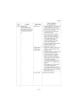
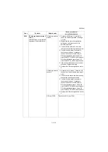
9010
Coin vender communica-
tion error
A communication error from
coin vender is detected 10
times in succession.
U206 setting
Set maintenance mode U206 to off when a
coin vender is not installed (see page 1-3-
84).
Coin vender control
PWB
1. Confirm that the wiring connector is
firmly connected and, if necessary,
connect the connector all the way in.
Coin vender control PWB and Engine
PWB (YC22)
2. If the wiring is disconnected, shorted or
grounded, replace the wiring.
3. Replace the Coin vender control PWB.
Engine PWB
1. Check the engine software and upgrade
to the latest, if necessary.
2. Replace the engine PWB (see page 1-5-
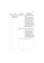
9040
DP lift motor going up error
When the DP lift motor is
driven, DP lift sensor 1 does
not turn on within 1500 pulse.
(Three recovery times.)
The above has been detected
5 times.
* : The number of detec-
tion should be
weighted with one for
the rise at job start and
two for the irregular
rise during transpot-
ing. The accumulated
number must be
cleared at completion
of a normal rise. The
default threshold is 5.
DP lift motor
1. Execute U906 Separating Operation
Release (see page 1-3-191).
2. Execute U243 Lift Motor to check the DP
motor operation (see page 1-3-98).
3. Check that the original document lift
guide can move upwards.
4. Confirm that the wiring connector is
firmly connected and, if necessary,
connect the connector all the way in.
DP lift motor and DP main PWB (YC5)
5. If the wiring is disconnected, shorted or
grounded, replace the wiring.
6. Replace the DP lift motor.
DP lift sensor 1
1. Execute U244 Lift L-Limit to check DP
switch (see page 1-3-99).
2. Check that the sensor and its mounting
bracket are correctly positioned.
3. Confirm that the wiring connector is
firmly connected and, if necessary,
connect the connector all the way in.
DP lift sensor 1 and DP main PWB
(YC4)
4. Replace the DP lift sensor 1.
DP main PWB
Replace the DP main PWB
Code
Contents
Related parts
Check procedures/
corrective measures
Summary of Contents for Copystar CS 3011i
Page 1: ...SERVICE MANUAL Published in September 2016 2RHSM 1 Rev 1 6 3011i 6 3511i ...
Page 4: ...This page is intentionally left blank ...
Page 10: ...This page is intentionally left blank ...
Page 78: ...2RG 2RH 1 2 51 B B A A B B A A B B A A Tray lower cover Pin Pin ...
Page 83: ...2RG 2RH 1 2 56 This page is intentionally left blank ...
Page 504: ...2RG 2RH 2 2 8 This page is intentionally left blank ...
Page 568: ...Installation Guide DP 7100 Document processor Installation Guide ...
Page 572: ...2 1mm 0mm ն ո պ ջ չ շ A D C B B A ...
Page 573: ...3 ռ ս վ ր ւ ց տ E A ...
Page 574: ...4 ք द I M3x8 փ F G M4x10 K J H A ...
Page 575: ...5 ON ध A ...
Page 577: ...7 շ յ ն ո D E B ...
Page 578: ...8 չ պ F G M4x10 H I M3x8 K J ջ B ...
Page 579: ...9 ռ B ...
Page 589: ...19 ո ն շ պ ջ չ 8 6 7 10 11 9 A B ...
Page 599: ...DP 7110 Document processor Installation Guide ...
Page 603: ...2 շ շ 2 շ 2 շ C M4x14 E ߑ ߒ ߓ ߔ ո շ 2 ߑ ն A ...
Page 604: ...3 ߘ ո ߕ ߗ ո չ պ ջ ߖ F G H M3x8 BLACK A ...
Page 605: ...4 ռ վ ր ւ ց ࠉտ ս I A ...
Page 606: ...5 J L փ ք द K M3x8 K M3x8 K M3x8 ध A ...
Page 607: ...6 ऩ प भ फ ब न म O N A ...
Page 608: ...7 ON य A ...
Page 610: ...9 շ ո շ 2 շ 2 շ 2 ߑ ն շ ߑ ߒ ߓ ߔ C M4x14 E B ...
Page 611: ...10 ߖ ߕ ߘ ߎ չ պ ջ ߗ F G ո H M3x8 BLACK B ...
Page 612: ...11 ռ ս տ ր ց վ I B ...
Page 613: ...12 ւ ք द ध न փ J L P K M3x8 K M3x8 B ...
Page 614: ...13 ऩ प फ O N B ...
Page 634: ...DP 7120 Document processor Installation Guide ...
Page 638: ...2 1mm 0mm ն շ ո չ ջ պ B B A D C A ...
Page 639: ...3 ռ ս վ տ ց ր E A ...
Page 640: ...4 G ւ F F ք փ H ON 10 mm 10 mm A ...
Page 642: ...6 շ ո յ ն D B ...
Page 643: ...7 չ E B ...
Page 644: ...8 F ON G պ F ջ ռ H 10 mm 10 mm B ...
Page 653: ...17 ղ ն շ ճ մ յ 2 6 7 3 4 5 A B ...
Page 655: ...19 չ ջ պ ս վ ռ 9 11 10 13 14 12 10 mm A B ...
Page 665: ...PF 791 500 x 2 Paper feeder Installation Guide ...
Page 673: ...PF 810 3000 sheet deck Installation Guide ...
Page 686: ...DF 791 3000 sheet finisher Installation Guide ...
Page 701: ...DF 7120 1000 sheet finisher Installation Guide ...
Page 705: ...2 մ յ ն 7 7 15 a b a a b b b a A ...
Page 706: ...3 ո շ չ պ A ...
Page 707: ...4 ջ ռ ս c d 14 c d c d 12 c d ջ ռ ս c d 14 c d c d 12 c d A ...
Page 708: ...5 վ ր D ց ON տ A ...
Page 710: ...7 L յ մ ն շ B ...
Page 712: ...9 ս ռ վ տ G B ...
Page 713: ...10 ր ց ւ b a 17 17 25 a b a a b b B ...
Page 714: ...11 ք փ द c d 24 c d c d 22 c d B ...
Page 715: ...12 न ध ऩ प B ...
Page 716: ...13 ब फ ON D B ...
Page 719: ...AK 740 Bridge unit Installation Guide ...
Page 721: ...MT 730 Mailbox Installation Guide ...
Page 736: ...PH 7A C D Punch unit Installation Guide ...
Page 757: ...DT 730 B Document tray Installation Guide ...
Page 759: ...5 2013 5 302LC56750 01 H F G D D 6 4 3 7 E C D D M4 8 M4 8 M4 8 M4 8 ...
Page 760: ...FAX System 12 Installation Guide ...