40
Example 6-5: Operation Mode Control on Drivers
Requirements: Defines the input port DIN3 as the operation mode control on drivers, and the operation
mode is ―-4‖ (pulse control mode) when DIN3 fails, and is ―-3‖ (instantaneous speed mode) when DIN3 is
valid. Table 6-13 describes the setup method.
Table 6-13 Settings on operation mode control on drivers
Numeric Display
Variable Name
Parameter Settings
d3.03
Din3_Function
Set to 000.4
d3.16
Din_Mode0
Set to 0.004 (-4)
d3.17
Din_Mode1
Set to 0.003 (-3)
d3.00
Store_Loop_Data
Set to 1
Note
: If the driver is required to operate in some mode with power on, one of the digital input must be set as
function
―Operation Mode Control‖. Then you can set the operation modes that require in the parameters
d3.16 or d3.37 in Group F003.
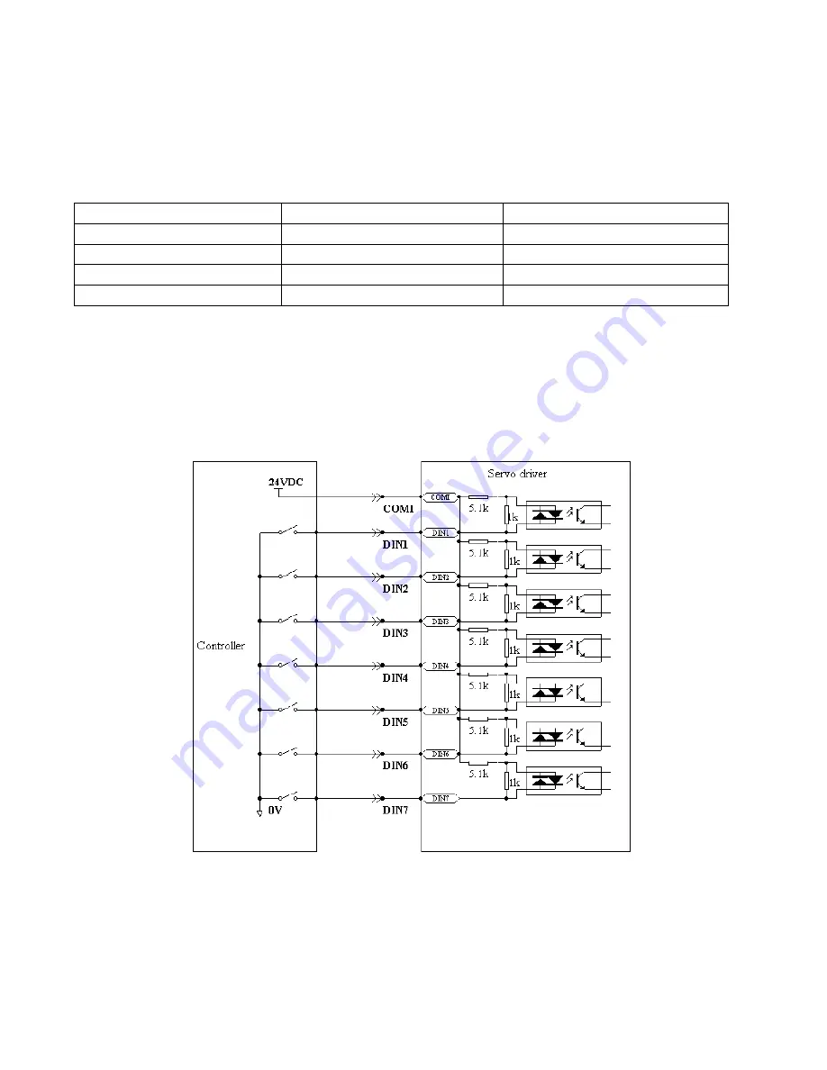
6.1.5 Wirings of Digital Input Port
1. NPN wiring diagram (to the controller that supports low level output)
Fig. 6-2 NPN wiring diagram (to the controller that supports low level output)
2. PNP wiring diagram (to the controller that supports high level output)
Summary of Contents for CD420
Page 8: ...8 1 3 3 Power Brake and Encoder cable of Motors...
Page 22: ...22 Fig 4 3 Separate regulation of bits...
Page 78: ...78...
Page 99: ...99 Chapter 11 Specification 11 1 Servo Drivers and Motors Selection Table...
Page 100: ...100 11 2 Servo Driver 11 2 1 Technical Specification Table for Servo Driver...
Page 101: ...101 11 2 2 Mechanical Dimension Diagram for Servo Driver...
Page 103: ...103 11 3 2 SMH80 Servo Motor...
Page 104: ...104 11 3 3 SMH110 Servo Motor 1 Technical Specification Table...
Page 105: ...105 2 Dimension Torque Curve...
Page 106: ...106 11 4 Wiring Diagram for Servo Motor Cable 11 4 1 Wiring Diagram for the Power Cable...
Page 107: ...107 11 4 2 Wiring Diagram for the Encoder Cable...


