73
(internal speed control 0)
d3.07
Din7_Function
Set to 020.0
(internal speed control 1)
d3.16
Din_Mode0
Set to 0.003 (3) mode
(speed mode with acceleration/deceleration)
d3.17
Din_Mode1
Set to 0.003 (-3) mode
(instantaneous speed mode)
d3.18
Din_Speed0_RPM
Set to 100 [rpm]
d3.19
Din_Speed1_RPM
Set to 200 [rpm]
d3.20
Din_Speed2_RPM
Set to 300 [rpm]
d3.21
Din_Speed3_RPM
Set to 400 [rpm]
d3.00
Store_Loop_Data
Set to 1
7.6 Internal Torque Control Mode (“4” Mode)
In the internal torque mode, only the current loop of the driver operates. Set d0.03 (CMD_q target current)
parameter directly to obtain the desired target torque. The prerequisite is that d3.30 must be set to 0. In this
case, the analog
–torque channel is invalid.
7.7 Homing Mode (“6” Mode)
1, Summary
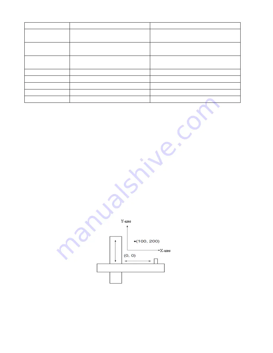
To make a system execute positioning in accordance with its absolute positioning, the first step is to define
the origin. For instance, as shown in the following XY plane, to navigate to (X, Y) = (100mm, 200mm), you
must define the origin of the machine firstly. It’s necessary to define the origin.
2, Procedure of homing
Use the following steps to homing:
1. Set the external I / O parameters, and then save.
2. Set the data for homing, and then save.
3. Execute homing.
Summary of Contents for CD420
Page 8: ...8 1 3 3 Power Brake and Encoder cable of Motors...
Page 22: ...22 Fig 4 3 Separate regulation of bits...
Page 78: ...78...
Page 99: ...99 Chapter 11 Specification 11 1 Servo Drivers and Motors Selection Table...
Page 100: ...100 11 2 Servo Driver 11 2 1 Technical Specification Table for Servo Driver...
Page 101: ...101 11 2 2 Mechanical Dimension Diagram for Servo Driver...
Page 103: ...103 11 3 2 SMH80 Servo Motor...
Page 104: ...104 11 3 3 SMH110 Servo Motor 1 Technical Specification Table...
Page 105: ...105 2 Dimension Torque Curve...
Page 106: ...106 11 4 Wiring Diagram for Servo Motor Cable 11 4 1 Wiring Diagram for the Power Cable...
Page 107: ...107 11 4 2 Wiring Diagram for the Encoder Cable...


