8. FRONT WHEEL, FRONT BRAKE
,
SUSPENSION
,
STEERING
8-6
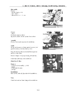
Disassembly
Remove:
--Footrest board(
→
2-
6
)
--Nut 1, Bolt 1
--Guard of
master cylinder
Remove:
--Bolt 2
Foot brake master cylinder.
Separate foot brake master cylinder from vehicle
Assembly
Reverse the removal procedure for installation.
NOTE
Do not put the master cylinder upside down to avoid
possible entrance of air into brake system.
Keep the master cylinder in the installation position
and fix it to the frame.
Refer to Chapter 1 for proper routing of brake hose.
Check brake efficiency after installation.
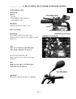
Brake Hose T-Pipe
Remove:
-- Front cover assembly. (
→
2-8)
--Bolt 3
--
Front right absorber
--T-Pipe
Installation
Reverse the removal procedure for installation
Note:
Check front and rear brake linkage after installation.
Summary of Contents for 500ATV
Page 1: ...Service Manual 500ATV 500ATV 2 4 4 ...
Page 16: ...1 SERVICE INFORMATION 1 14 ...
Page 17: ...1 SERVICE INFORMATION 1 15 1 ...
Page 18: ...1 SERVICE INFORMATION 1 16 ...
Page 32: ...2 Vehicle body Muffler 2 14 Visible Parts ...
Page 53: ...4 COOLING SYSTEM 4 7 Cooling System Chart 4 ...
Page 63: ...6 Engine Removal Inspection Installation 6 1 Wu Yang 500 CC engine maintenance manual 6 ...
Page 71: ......
Page 72: ......
Page 73: ...6 Engine Removal Inspection Installation 6 11 Engine information 6 ...
Page 190: ...11 BATTERY CHARGING SYSTEM 11 9 Layout for All Electricity Equipment in Vehicle ...
Page 192: ...12 IGNITION SYSTEM 12 2 Ignition System Diagram ...
Page 200: ...12 IGNITION SYSTEM 12 10 Layout for Ignition System Equipment in Vehicle ...
Page 212: ...13 Lighting Instruments Switches 13 12 500ATV Circuit Diagram ...


