8. FRONT WHEEL, FRONT BRAKE
,
SUSPENSION
,
STEERING
8-10
Disassembly:
Note:
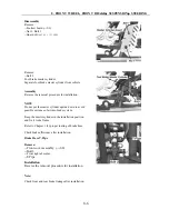
Replacing the front shock absorber does not require removal of other parts.
Remove Bolt (24) and Nut (10)
Remove front right shock absorber.
Inspection:
Oil leakage, aged oil seal, damage
→
Replace
Installation:
Reverse the removal procedure for installation.
Refer to
Front Right Shock Absorber
for disassembly, installation and inspection of
Front Left
Absorber.
Suspension Arms
Note: This vehicle has 8 suspension arms. The removal, disassembly, inspection and installation of the
8 arms are the same.
This service manual will only introduce the removal, disassembly, inspection and installation of
Front
Left Upper Arm, Front Left Lower Arm
.
Refer to
Front Left Upper Arm, Front Left Lower Arm
for removal, disassembly, inspection and
installation of other suspension arms.
Front Right Arm
Disassembly
Remove:
--Front right absorber (
→
8-8)
--Bolt (23) and Nut (10);
--Bolt (6) and Nut (10)
--Bolt (6) and Nut (10)
Remove wheel, brake caliper and wheel hub before removing absorber;
Remove tie-rod before removing bolts;
Pull out front
right
knuckle from front right drive shaft before removing front right arm.
Inspection
Ball Pin
Check if upper
arm ball
(21) for front right upper arm (18) and lower
arm ball
for front right lower arm
(4) can turn freely in all directions.
Check clearance of upper and lower balls.
Clearance out of range, no free turning:
→
Replace Arm Ball
Right Knuckle
Inspection:
Damaged knuckle:
→
Replace
Check wheel hub bearing for free turning and clearance.
Bearing cannot turn freely or clearance out of range:
→
Replace
Summary of Contents for 500ATV
Page 1: ...Service Manual 500ATV 500ATV 2 4 4 ...
Page 16: ...1 SERVICE INFORMATION 1 14 ...
Page 17: ...1 SERVICE INFORMATION 1 15 1 ...
Page 18: ...1 SERVICE INFORMATION 1 16 ...
Page 32: ...2 Vehicle body Muffler 2 14 Visible Parts ...
Page 53: ...4 COOLING SYSTEM 4 7 Cooling System Chart 4 ...
Page 63: ...6 Engine Removal Inspection Installation 6 1 Wu Yang 500 CC engine maintenance manual 6 ...
Page 71: ......
Page 72: ......
Page 73: ...6 Engine Removal Inspection Installation 6 11 Engine information 6 ...
Page 190: ...11 BATTERY CHARGING SYSTEM 11 9 Layout for All Electricity Equipment in Vehicle ...
Page 192: ...12 IGNITION SYSTEM 12 2 Ignition System Diagram ...
Page 200: ...12 IGNITION SYSTEM 12 10 Layout for Ignition System Equipment in Vehicle ...
Page 212: ...13 Lighting Instruments Switches 13 12 500ATV Circuit Diagram ...


