background image

VERITAS Vision System Components

Z370584 Rev. D

3-2

System Components

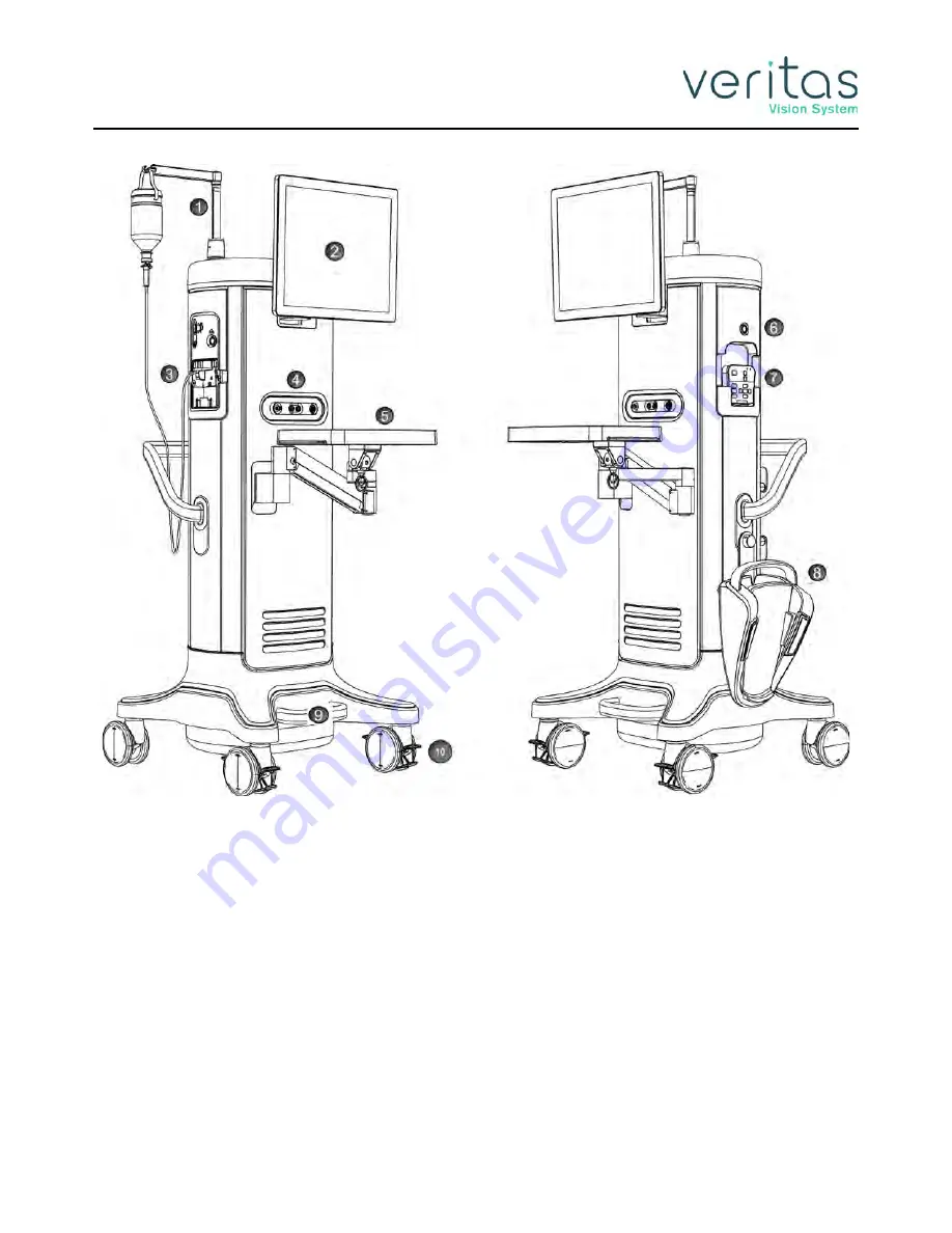
Figure 3-1 — VERITAS Vision System (front)

1. Programmable IV Pole

6. On/Off button

2. Touchscreen monitor

7. VERITAS Remote Control storage

3. Tubing Pack inserted

8. Foot Pedal stored on J-Hook

4. Front Panel Connections (see 

Figure 4-1

)

9. Foot Loop for system repositioning

5. Mayo Tray 

10. Locking Wheels

Summary of Contents for Veritas

Page 1: ...Z370584 Rev D 09 2020 Johnson Johnson Surgical Vision Inc 2020 Software Release 8 000 OPERATOR MANUAL...

Page 2: ...Z370584 Rev D This page was intentionally left blank...

Page 3: ...at while every effort has been made to ensure the data provided in this document are accurate the information figures illustrations tables specifications and schematics contained herein are subject to...

Page 4: ...Z370584 Rev D This page was intentionally left blank...

Page 5: ...Warnings Cautions and Other Residual Risks Cautions 2 1 Warnings 2 3 Residual Risks 2 8 Regulatory Symbol Definitions 2 8 Regulatory Compliance Statements 2 10 Federal Communications Commission FCC Co...

Page 6: ...al 3 17 4 Surgery Start Up VERITAS Vision System Setup 4 1 Front and Rear Panel Connections 4 2 IV Pole Setup 4 4 Handpiece Setup 4 4 Phacoemulsification Handpiece Setup VERITAS Swivel 4 5 Phacoemulsi...

Page 7: ...und Levels 5 39 Default Settings 5 39 Surgeon Assign Order 5 41 6 Program Settings Create a New Program 6 1 Delete a Program 6 4 Edit a Program Name 6 5 Lock a Program 6 5 Copy a Surgeon Program 6 5 A...

Page 8: ...ing the IV Pole 7 2 Event Log 7 3 Wireless Foot Pedal Setup 7 4 VERITAS Foot Pedal and Advanced Linear Pedal 7 4 Advanced Control Pedal 7 7 VERITAS Remote Control Setup 7 9 VERITAS Remote Control Pair...

Page 9: ...Replacement Procedure 10 2 Battery Replacement VERITAS Foot Pedal and Advanced Linear Pedal 10 3 Battery Replacement VERITAS Remote Control 10 4 Charging Options for Wireless Foot Pedals 10 4 Trouble...

Page 10: ...ecifications 12 19 Vitrectomy Specifications 12 20 Diathermy Specifications 12 20 Diathermy Power Graphs 12 21 Diathermy Power versus Load Impedance 12 24 Phaco Power Graphs 12 25 Phaco Tip Velocity 1...

Page 11: ...1 4 Clinical Benefits on page 1 5 Performance Characteristics on page 1 5 Device Description on page 1 6 Introduction The VERITAS Vision System is a premium cataract system with the intended use of ph...

Page 12: ...roduction Z370584 Rev D 1 2 Introduction Figure 1 1 VERITAS Vision System front 1 Programmable IV Pole 3 Front Panel Connections see Figure 4 1 2 Tubing Pack inserted 4 Foot Loop for system reposition...

Page 13: ...o be connected with the console Surgical instrument without Ultrasound assistance see separate Instructions for Use c Diathermy Handpieces to be connected with the console Bi polar surgical HF instrum...

Page 14: ...be a contraindication to cataract surgery Undesirable Side Effects Complications that may be associated with the VERITAS Vision System include corneal burn infection inflammation corneal edema broken...

Page 15: ...e standard square wave pulse by increasing the amplitude of the first millisecond of the on time kick This technology then sets the remaining part of the on time to the standard power setting This res...

Page 16: ...handpiece The prime tune mode allows the system to prime and tune the handpiece at the same time Dual Pump The system provides a fluid aspiration system that uses either a peristaltic flow based pump...

Page 17: ...Advanced Infusion Program This allows different users to preset their preferences or individual users to select setups for different procedures including a personalized initial operating mode MMP Mult...

Page 18: ...using little or no ultrasound The WHITESTAR Technology changes the thermal properties and improves control of the lens without reducing the cutting power or changing technique or efficiency Irrigation...

Page 19: ...ng of the occlusion while the vacuum is at a high level can lead to a post occlusion surge When CASE is on the system monitors the actual vacuum levels When the vacuum exceeds a specific threshold for...

Page 20: ...ional steam autoclave methods Figure 1 2 VERITAS Swivel Handpiece WHITESTAR Handpiece The design of the WHITESTAR phaco handpiece has a straight through aspiration channel for more efficient removal o...

Page 21: ...y in phacoemulsification Occlusion Mode Phaco The Occlusion mode phaco regulates the vacuum rise time following an occlusion of the phaco tip without limiting the choice of aspiration rate through an...

Page 22: ...Z370584 Rev D 1 12 This page was intentionally left blank...

Page 23: ...tions carefully before using the system in surgery Do not use extension cords with your system Do not overload your electrical receptacle outlet The instrument has ventilation openings at the rear of...

Page 24: ...ch any solid material while in use Handpieces can be extremely hot immediately after sterilization Use care and caution when handling Do not activate the phaco handpiece and vitrectomy cutter with the...

Page 25: ...system performance See Charging Options for Wireless Foot Pedals on page 10 4 Warnings All personnel who might operate this equipment must read and understand the instructions in this manual before th...

Page 26: ...ly force the pole height because this could cause incorrect indication of bottle height and patient injury Please note that when Cont Irr Auto Off is enabled a significantly large wound leakage or air...

Page 27: ...system Call JJSV customer service to order a new cord Disconnect the power before you service the equipment Remove the power cord from the power outlet when the equipment is not in use Do not obstruct...

Page 28: ...alt solution free flow can result in a slip hazard The Advanced Infusion feature must only be used with bottles and is not to be used with bags Using the Advanced Infusion feature with a bag may resul...

Page 29: ...or stacked with other equipment and that if adjacent or stacked use is necessary the VERITAS Vision System should be observed to verify normal operation in the configuration in which it will be used D...

Page 30: ...l warning sign IEC 60601 1 2005 AMD1 2012 Medical electrical equipment Part 1 General requirements for basic safety and essential performance Symbol reference Table D 2 2 ISO 7010 W001 Consult instruc...

Page 31: ...Symbols to be used with medical device labels labeling and information to be supplied Part 1 General requirements Symbol reference 5 1 1 Medical Device MedTech Europe Guidance on Use of Symbols to In...

Page 32: ...ful interference when the equipment is operated in a commercial environment This equipment generates uses and can radiate radio frequency energy and if not installed and used in accordance with the in...

Page 33: ...ks or endangerments by nonprofessional disposal the disposal of this product including any accessories must comply with valid practices as outlined in Directive 2012 19 EU and local regulations Contac...

Page 34: ...iction of Chemicals EU REACh For information related to Article 33 of the EU REACh regulation EC No 1907 2006 please contact JJSV at ps_jjvs its jnj com Names and Contents of Toxic Hazardous Substance...

Page 35: ...se accessories where possible Recycling packaging materials of accessories where possible At the end of the surgical day unplug the power cord from the wall Region Mailbox Asia Pacific JJSV APAC Compl...

Page 36: ...Z370584 Rev D 2 14 This page was intentionally left blank...

Page 37: ...u not from the shipper JJSV Your JJSV representative will contact you to schedule both the installation and the in service training when you receive your new VERITAS Vision System We suggest that you...

Page 38: ...ERITAS Vision System front 1 Programmable IV Pole 6 On Off button 2 Touchscreen monitor 7 VERITAS Remote Control storage 3 Tubing Pack inserted 8 Foot Pedal stored on J Hook 4 Front Panel Connections...

Page 39: ...re 3 2 VERITAS Vision System back 1 Power Cord Wrap Allows for wrapping and storage of the console power cord 3 Storage Compartment Allows for storage of miscellaneous accessories and foot pedal cable...

Page 40: ...bing administration set with an attached sealed drain bag Test chamber to test and prime tune the phaco handpiece Mayo tray drape to cover the Mayo tray and arm Monitor drape to cover the front of the...

Page 41: ...res of the FUSION Dual Pump Tubing Pack with smaller bore aspiration tubing It also features a male irrigation luer lock fitting to help secure the connection to a handpiece possessing the mating feat...

Page 42: ...e balanced salt solution bottle Compared to gravity only tubing packs the Advanced Infusion feature allows greater irrigation pressure at the same IV pole height Figure 3 4 VERITAS Advanced Infusion T...

Page 43: ...FUSION Dual Pump DP Tubing Pack OPO73 Figure 3 5 includes support for the flow based peristaltic aspiration pump and the vacuum based Venturi aspiration pump Figure 3 5 FUSION Dual Pump Tubing Pack 1...

Page 44: ...e The foot pedal cable attaches to the foot pedal connector on the rear of the console The VERITAS Foot Pedal Advanced Control Pedal and the Advanced Linear Pedal can also be set up with a wireless co...

Page 45: ...oot Pedal 1 Handle 4 Treadle 7 Wireless Indicator 2 Left Right Top Switches 5 Heel Rest 8 Battery Indicator 3 Left Right Side Switches 6 Cable Connector 1 Handle 4 Right toe switch 7 Heel rest 2 Cable...

Page 46: ...edal 1 Left yaw 4 Adjustable Heel Stop 7 Right yaw 10 Wireless Indicator 2 Wake up button 5 Right heel switch 8 Handle 11 Battery Indicator 3 Left heel switch 6 Lights 9 Treadle 1 Handle 4 Heel rest 7...

Page 47: ...vanced Linear Pedal 1 To remove the handle press the clips on either side of the handle Figure 3 10 Foot Pedal Handle Diagram 2 Remove the cover of the handle 3 Remove the screws and store the screws...

Page 48: ...rol Pedal has two Yaw switches Figure 3 11 Advanced Control Pedal Pitch and Yaw Positions NOTE The foot pedal position determines the function that is delivered by the handpiece which depends on the m...

Page 49: ...584 Rev D Foot Pedal 3 13 Foot Pedal Storage The Advanced Linear Pedal and VERITAS Foot Pedal can be stored on the system on the J Hook as shown in Figure 3 1 Figure 3 2 and Figure 3 12 below Figure 3...

Page 50: ...on the treadle which may be more comfortable for some users The VERITAS Heel Insert attaches to the VERITAS Foot Pedal by magnetic attraction When not in use the VERITAS Heel Insert can be stored in t...

Page 51: ...essurized infusion The height measurement is relative to the distance from the irrigation valve to the center of the drip chamber The IV pole height for each fluidic mode or submode Phaco I A Vitrecto...

Page 52: ...NOTE After four to six minutes of idle time the VERITAS Remote Control goes into a power save mode To turn the VERITAS Remote Control on press any button 1 Reload 7 Mode Submode Down 2 IV Pole Up Down...

Page 53: ...w Figure 3 15 VERITAS Remote Control Module Storage Surgical Media Center SMC Optional The optional Surgical Media Center SMC is used to record the surgery and the instrument settings to be viewed at...

Page 54: ...Z370584 Rev D 3 18 This page was intentionally left blank...

Page 55: ...s is a general overview of the steps to prepare the VERITAS Vision System for surgery 1 Attach the power cord to the power cord connector on the rear panel of the console see Figure 3 2 and Figure 4 2...

Page 56: ...Tune on page 4 14 9 Perform the final test of the fluidics and the handpiece integrity with the foot pedal see Verify Irrigation Aspiration Balance on page 4 17 Front and Rear Panel Connections This s...

Page 57: ...el Connections 4 3 Figure 4 2 Rear Panel Connections 1 USB port 5 Power switch 2 Communication port 6 Fuse holder 3 Foot pedal connector 7 Power cord connector 4 Potential equalizer CAUTION Securely a...

Page 58: ...can also use the rocker switch on the console 5 Attach the I A tubing to the handpiece NOTE To ensure the bottle height does not change when you select I A after vitrectomy during surgery check the Bo...

Page 59: ...gure 3 1 and Figure 4 1 Ensure there is no moisture on the connectors prior to attaching Moisture prevents the handpiece from operating properly WARNING Sterility assurance is the responsibility of th...

Page 60: ...chnology phaco settings 5 Insert the male luer end of the irrigation tubing into the phaco handpiece 6 Attach the female luer fitting end of the aspiration tubing to the phaco handpiece NOTE To protec...

Page 61: ...Figure 3 1 and Figure 4 1 5 Ensure there is no moisture on the connectors prior to attaching Moisture prevents the handpiece from operating properly WARNING Sterility assurance is the responsibility...

Page 62: ...ogy phaco settings 6 Insert the male luer end of the irrigation tubing into the phaco handpiece 7 Attach the female luer fitting end of the aspiration tubing to the phaco handpiece NOTE To protect the...

Page 63: ...available with the OPOS20L or any 20 gauge LAMINAR phaco tip Figure 4 9 I A Handpiece Assembly Diathermy Handpiece Setup 1 Attach the diathermy cord to the diathermy forceps or pencil 2 Attach the dia...

Page 64: ...23 Gauge Limbal Infusion tip if desired 2 Use the instructions provided with the vitrectomy cutter to assemble the handpiece Figure 4 12 Vitrectomy Cutter 3 Attach the connector to the vitrectomy rec...

Page 65: ...he main menu you can Select a Surgeon Program and begin surgery based on the values of that program Access the Settings screen where you can edit programs and setup operating parameters Access the Con...

Page 66: ...the Install Pack Screen is shown Figure 4 14 Install Pack Screen 3 Install a tubing pack as shown on the screen in Figure 4 14 by inserting it into the fluidics panel until the system activates the l...

Page 67: ...n with Cup Fill Controls Highlighted 3 Use the up arrow to cycle through the three available amounts of solution to be dispensed You can choose from 30 cc 60 cc 90 cc NOTE The fill rate and time is ba...

Page 68: ...ms a vacuum check and tests and characterizes the phaco handpiece You can select Continuous Irrigation to allow fluid to free flow from the bottle to collect fluid The design of I A Prime allows for a...

Page 69: ...d tune you only need to select and run the tune CAUTION Do not activate the phaco handpiece and vitrectomy cutter with the tip in the air Exposure of the tip to air drastically reduces the useful life...

Page 70: ...ht fixtures or equipment do not block the movement of the IV pole Do not manually adjust the IV pole height with the remote control or rocker switch during Prime Tune sequences 7 Watch the fluid fill...

Page 71: ...n line just below the handpiece while you press and hold the foot pedal in position 2 3 The actual vacuum level should rise to the preset level 4 Release the aspiration line and then watch the test ch...

Page 72: ...igation tubing and the aspiration tubing of the tubing pack together 2 Tap Prime on the Prime Tune screen 3 Tap the VIT button to access the Vitrectomy mode 4 Connect the I A tubing to the vitrectomy...

Page 73: ...move quickly and easily through all the system functions and system operations Panels organize the text on the display screen The top panel shows current status EPT or EFX timer configuration options...

Page 74: ...f the check out procedure is to verify that installation of the system is complete and the system is operating properly You must perform the check out procedure prior to the first case of the day as o...

Page 75: ...chamber to ensure the test chamber does not collapse A dent or dimple in the test chamber is normal 13 To test irrigation pinch the irrigation tubing just below the phaco handpiece and watch for the t...

Page 76: ...e of motion of the handpiece the cutter blade operates 7 Vitrectomy check out is complete Pre operative Sterilization Prior to each surgical case sterilize the system instruments with the recommended...

Page 77: ...ical screen You can tap the timer to view the detailed timer pop up with EPT EFX UST and DT timers of the surgical case Each timer indicates the following Effective Phaco Time EPT EPT is ultrasound ti...

Page 78: ...more detail than 15 Min Select a longer time interval for an overview of the surgery or sessions such as 1 hour or 2 hours This view provides less detail but gives you a better indication of the trend...

Page 79: ...data for the current surgical case is only available after selecting Next Case End Case Tap Next Case to end the current surgical case and start a new one and install a new tubing pack NOTE Use a new...

Page 80: ...me System Shutdown The following is a general overview of the steps to be taken to shut the system down after surgery 1 Tap End Case 2 Tap Shutdown At the prompt tap Yes 3 Wait for shutdown sequence t...

Page 81: ...page 5 3 Edit a Surgeon on page 5 3 Edit Surgeon Settings on page 5 4 Foot Pedal Setup on page 5 6 Set Sound Levels on page 5 39 Surgeon Assign Order on page 5 41 When the system is used for the first...

Page 82: ...rgeon To create a new surgeon 1 Tap on Select Surgeon The keyboard screen opens 2 Enter the name of the surgeon 3 Tap Enter to save the new surgeon and then exit the keyboard screen The new surgeon is...

Page 83: ...To remove a surgeon name from the list 1 Select the name of the surgeon 2 Tap on Select Surgeon 3 At the confirmation dialog box select Yes Edit a Surgeon 1 Select a surgeon from the list Figure 5 3 S...

Page 84: ...Surgeon Settings Figure 5 4 Edit Surgeon Name Screen 3 Edit the name 4 Tap Enter Edit Surgeon Settings To define venting Tap for Irrigation and Cont Irr Auto Off setting preferences for the selected s...

Page 85: ...Surgeon Settings Z370584 Rev D Edit Surgeon Settings 5 5 Figure 5 5 Select Surgeon 2 Tap the Surgeon Settings option on Select Surgeon The Surgeon Settings screen appears...

Page 86: ...1 2 or 3 Default is Off When this feature is enabled continuous irrigation will automatically turn on when the foot pedal is pressed and automatically turn off when the handpiece is removed from the...

Page 87: ...itrectomy Foot Pedal Modes on page 5 8 Single Linear Foot Pedal Connections on page 5 8 Single Linear Foot Pedal Switch Assignment on page 5 8 Single Linear Foot Pedal Threshold Configuration on page...

Page 88: ...h surgeon For Phaco and Vitrectomy foot pedal settings the switches are set per submode Follow the steps below to assign functions to the foot pedal switches NOTE In addition to showing the type and s...

Page 89: ...switches In addition both Phaco and Vitrectomy modes have individual settings per submode for the foot pedal switches The Single Linear Foot Pedal screen displays the settings for the pedal linear mot...

Page 90: ...sign or change the action for each of the four switches 4 Select the major mode and then the applicable submode 5 Tap the buttons under each switch name to assign or change the action for that switch...

Page 91: ...nt program in the list Surgeon Program Down Selects the surgeon program below the current program in the list Previous Major Mode Changes to the previous surgical mode Next Major Mode Changes to the n...

Page 92: ...se steps to configure the thresholds for the foot pedal 1 On the Surgeons and Programs screen tap 2 Tap the Thresholds button 3 Use the arrow buttons to set the threshold for position 1 2 or 3 The sys...

Page 93: ...ck is a physical and audible click as you move the foot pedal to the next or previous position 5 Tap Save to retain the settings Single Linear Foot Pedal Calibration and Testing Follow these steps to...

Page 94: ...ss the foot pedal down fully to position 3 As the foot pedal travels through positions 1 and 2 to position 3 the progress bar shows its current state When the pedal reaches the bottom of position 3 th...

Page 95: ...owing topics for setting up a VERITAS Foot Pedal VERITAS Foot Pedal Connections on page 5 16 VERITAS Foot Pedal Switch Assignment on page 5 16 Advanced Control Pedal Threshold Configuration on page 5...

Page 96: ...end of the cable to the foot pedal connector on the rear panel of the system see Figure 3 2 and Figure 4 2 To use the foot pedal wirelessly see Wireless Foot Pedal Setup on page 7 4 VERITAS Foot Peda...

Page 97: ...have individual settings per submode for the foot pedal switches The VERITAS Foot Pedal screen displays the settings for the pedal linear motion Pitch and function assignments for each of the four sw...

Page 98: ...stem displays a switch assignment dialog box with the text of the current switch assignment shown in green NOTE If you select Next Major Mode Previous Major Mode Next Active Mode or Previous Active Mo...

Page 99: ...gram in the list Surgeon Program Down Selects the surgeon program below the current program in the list Previous Major Mode Changes to the previous surgical mode Next Major Mode Changes to the next su...

Page 100: ...ition to showing the type and status of the foot pedal the foot pedal icon shown below in the top of the screen also allows access to the Foot Pedal Settings screen 1 On the Surgeons and Programs scre...

Page 101: ...old for each of the foot pedal pitch zones P1 is the first zone P2 is the second and P3 is the final zone 4 Check the Feedback checkbox to enable foot pedal feedback Feedback is a physical and audible...

Page 102: ...re 5 19 VERITAS Foot Pedal Test Screen NOTE In addition to showing the type and status of the foot pedal the foot pedal icon shown below in the top of the screen also allows access to the Foot Pedal S...

Page 103: ...reen 5 Tap the Finished button when you complete the testing of your foot switch 6 Tap Exit to close the Foot Pedal Set Up screen Advanced Control Pedal Setup This section presents the following topic...

Page 104: ...r on the rear panel of the system see Figure 3 2 and Figure 4 2 To use the foot pedal wireless see Wireless Foot Pedal Setup on page 7 4 Advanced Control Pedal Switch Assignment The Advanced Control P...

Page 105: ...ndividual settings for the foot pedal switches In addition both Phaco and Vitrectomy modes have individual settings per submode for the foot pedal switches Figure 5 21 Advanced Control Pedal Phaco Sum...

Page 106: ...he system displays a switch assignment dialog box with the text of the current switch assignment shown in green NOTE If you select Next Major Mode Previous Major Mode Next Active Mode or Previous Acti...

Page 107: ...program in the list Surgeon Program Down Selects the surgeon program below the current program in the list Previous Major Mode Changes to the previous surgical mode Next Major Mode Changes to the nex...

Page 108: ...ssing the foot pedal icon shown below near the top of the screen 1 On the Surgeons and Programs screen tap 2 Tap the Thresholds button under Foot Pedal The system displays the foot pedal thresholds sc...

Page 109: ...the current value 4 Use the up and down arrows to set the threshold for the left and right yaw controls The threshold determines how far the user needs to move the pedal before the switch is activated...

Page 110: ...below near the top of the screen 1 On the Surgeons and Programs screen tap 2 Tap the Calibration button Figure 5 25 Advanced Control Pedal Calibration 3 With your foot off the foot pedal tap the Phase...

Page 111: ...ns green and its Off button turns white When you release the switch the On button for that switch turns white and its Off button turns green 9 Tap Finished when you complete the testing of your foot s...

Page 112: ...ach the other end of the cable to the foot pedal connector on the rear panel of the system see Figure 3 2 and Figure 4 2 To use the foot pedal wirelessly see Wireless Foot Pedal Setup on page 7 4 Adva...

Page 113: ...as individual settings for the foot pedal switches In addition both Phaco and Vitrectomy modes have individual settings per submode for the foot pedal switches Figure 5 28 Advanced Linear Pedal Summar...

Page 114: ...switch to assign or change the action for that switch The system displays a switch assignment dialog box with the text of the current switch assignment shown in green NOTE If you select Next Major Mod...

Page 115: ...program in the list Surgeon Program Down Selects the surgeon program below the current program in the list Previous Major Mode Changes to the previous surgical mode Next Major Mode Changes to the next...

Page 116: ...ocedure below you can access the Advanced Linear Pedal Summary screen by pressing the foot pedal icon shown below near the top of the screen 1 On the Surgeons and Programs screen tap 2 Tap the Thresho...

Page 117: ...shold for each of the foot pedal pitch zones P1 is the first zone P2 is the second and P3 is the final zone 4 Check the Feedback checkbox to enable foot pedal feedback Feedback is a physical and audib...

Page 118: ...d Linear Pedal Summary screen by pressing the foot pedal icon shown below near the top of the screen 1 On the Surgeons and Programs screen tap 2 Tap the Test button 3 Press the foot pedal down fully t...

Page 119: ...des two sets of tone options VERITAS and WHITESTAR SIGNATURE PRO You can select the tone preference by tapping either VERITAS or WHITESTAR SIGNATURE PRO Once you select your preferred tone you can hea...

Page 120: ...rgeon 2 Tap Figure 5 33 Sound Settings Screen 3 Use the sliders to adjust the volume for Master Volume Instrument Confirmation 4 Use the buttons on the right side to turn sounds on or off for the diff...

Page 121: ...Assign Order 5 41 Surgeon Assign Order 1 Select a surgeon 2 Use or to move the surgeon names up or down on the Surgeons and Programs screen Figure 5 34 Surgeons and Programs Screen 3 Repeat the steps...

Page 122: ...Z370584 Rev D 5 42 This page was intentionally left blank...

Page 123: ...ult Settings on page 6 13 Phaco Power Settings on page 6 19 WHITESTAR Technology on page 6 21 FUSION Fluidics Phaco on page 6 27 Create a New Program When you create a new surgeon the system automatic...

Page 124: ...Create a New Program Z370584 Rev D 6 2 Program Settings Figure 6 1 Surgeons and Programs Screen 1 On Select Program tap...

Page 125: ...Program Settings Z370584 Rev D Create a New Program 6 3 Figure 6 2 Create New Program 2 Enter a program name and tap Enter or tap Standard Names select a program name from the list and tap Enter...

Page 126: ...n You cannot delete a program if it is the only program defined for a custom surgeon You also cannot delete the default 19 gauge 20 gauge and 21 gauge programs from the Standard Surgeon If you delete...

Page 127: ...rogram you cannot unlock the program You can edit the locked program to use different settings during surgery but you cannot save or overwrite the program settings once done You cannot delete the defa...

Page 128: ...ft of the Settings screen see Figure 6 6 Program settings include the following Advanced Infusion If this checkbox is checked enabled program settings are customized to use the VERITAS Advanced Infusi...

Page 129: ...he next active submode NOTE There must be at least one Phaco submode active in a program If there is only one active Phaco submode its Active checkbox will be grayed out for unchecking disabling see F...

Page 130: ...Venturi 5 Use the up and down arrows to set the Aspiration rate 10 to 60 6 Use the up and down arrows to set the Vacuum If you are using Venturi the range is 0 to 600 If you are using Peristaltic the...

Page 131: ...e screen outlined in red in Figure 6 7 to customize the submode name 4 Select the pump type Peristaltic or Venturi 5 Use the up and down arrows to set the Aspiration rate 0 to 60 6 Use the up and down...

Page 132: ...set the Aspiration rate 0 to 60 6 Use the up and down arrows to set the Vacuum If you are using Venturi the range is 0 to 600 If you are using Peristaltic the range is 0 to 650 7 Use the up and down a...

Page 133: ...e to save the program Diathermy DIA 1 Tap to open the Settings screen 2 Select a Diathermy submode on the left Figure 6 9 Figure 6 9 Diathermy Power Submode 3 If desired tap the submode name at the to...

Page 134: ...m Settings Advanced Infusion 1 Tap to open the Settings screen 2 When using the Advanced Infusion Tubing Pack VRT AI the Advanced Infusion checkbox must be checked as outlined in red in Figure 6 10 be...

Page 135: ...5 less than occlusion threshold setting 0 or 5 less than occlusion threshold setting 0 or 5 less than occlusion threshold setting Max vacuum peristaltic and Venturi Unoccluded mmHg 60 or 120 when CASE...

Page 136: ...ps 6 pps 6 pps 6 pps 6 pps Long pulse rate occluded and unoccluded 1 6 pps 4 pps 4 pps 4 pps 4 pps Pulse Shape Parameters Kick Low 5 5 5 5 Kick High 5 5 5 5 Low Power Limit 0 0 0 0 High Power Limit 80...

Page 137: ...setting 0 or 5 less than occlusion threshold setting 0 or 5 less than occlusion threshold setting 0 or 5 less than occlusion threshold setting Max vacuum peristaltic and Venturi Unoccluded mmHg 80 or...

Page 138: ...6 pps Long pulse rate occluded and unoccluded 1 6 pps 4 pps 4 pps 4 pps 4 pps Pulse Shape Setting WHITESTAR ICE On Off Off Off Off Off Pulse Shape Parameters Kick Low 5 5 5 5 Kick High 5 5 5 5 Low Pow...

Page 139: ...setting 0 or 5 less than occlusion threshold setting 0 or 5 less than occlusion threshold setting 0 or 5 less than occlusion threshold setting Max vacuum peristaltic and Venturi Unoccluded mmHg 100 o...

Page 140: ...Long pulse rate occluded and unoccluded 1 6 pps 4 pps 4 pps 4 pps 4 pps Pulse Shape Setting WHITESTAR ICE On Off Off Off Off Off Pulse Shape Parameters Kick Low 5 5 5 5 Kick High 5 5 5 5 Low Power Li...

Page 141: ...High Power Pulse Single Burst panel only Multiple Burst panel only Continuous Burst From the Phaco Settings screen tap to display the Phaco Power selection Figure 6 11 Phaco Power Settings In addition...

Page 142: ...number of pps is on the button to the right of the Short Pulse button To set the Short Pulse range 1 Tap the Short Pulse button 2 Tap on the pulse setting number A Settings dialog box opens 3 Tap the...

Page 143: ...econd Continuous Burst Phaco Power Continuous Burst can deliver an ultrasonic burst duration from 50 to 150 ms As you press the foot pedal through position 3 the bursts get closer together At the maxi...

Page 144: ...Technology Parameter Settings Figure 6 12 Duty Cycle Setting Pulse On Time ms Pulse Off Time ms Duty Cycle Pulse Rate pps 6 12 6 12 33 55 4 8 4 8 33 83 6 4 6 4 60 100 6 8 6 8 43 71 8 4 8 4 67 83 4 24...

Page 145: ...hrough the power delivery zone The zone is divided into four equal size quadrants and a different duty cycle can be applied in each quadrant Variable WS You can also use the sliding adjustments to cre...

Page 146: ...WHITESTAR Technology Z370584 Rev D 6 24 Program Settings Figure 6 14 Duty Cycles for Variable WS...

Page 147: ...of the two milliseconds of the on time kick and then setting the remaining part of the on time to the standard power setting This is repeated for each on time period resulting in increased control an...

Page 148: ...amplitude or amount of the applied phaco power kick in the two milliseconds of phaco power either in the low end or the high end of the power range As the phaco power increases from the Low Power Lim...

Page 149: ...CASE vacuum level When the occlusion clears the system automatically restores to the original programmed maximum vacuum setting It is possible to have a different maximum vacuum setting when the tip o...

Page 150: ...ou can set different aspiration rates for occluded aspiration as opposed to unoccluded aspiration You can set a different vacuum rise time for when the phaco tip occludes without changing the aspirati...

Page 151: ...Fluidics Phaco 6 29 Figure 6 19 Occlusion Mode Settings Screen 4 Use the up and down arrows to adjust the pump ramp 5 Tap the FUSION button 6 On the FUSION screen use the up and down arrows to adjust...

Page 152: ...sion mode phaco there is an additional control panel for vacuum The vacuum threshold setting lets you choose the vacuum level at which occluded settings take effect To adjust the occluded vacuum thres...

Page 153: ...cclusion mode phaco tap the up or down arrows to increase or decrease the occluded aspiration rate Or 1 Tap The Settings screen opens 2 Tap the up or down arrows to increase or decrease the occluded a...

Page 154: ...usion threshold then the system uses the occlusion settings You cannot set the nonzero start value higher than the occlusion threshold 1 Tap the Settings button 2 Tap to change other power settings A...

Page 155: ...he aspiration tip and gives you full control if the tip accidentally grabs the capsule or iris The fluidics system maintains the desired vacuum level when you hold the foot pedal at a constant positio...

Page 156: ...tting Lower Threshold Down After the occlusion clears the vacuum level drops to the lower vacuum threshold setting to allow the occlusion to safely clear and then gradually returns to the previous lev...

Page 157: ...k flow of fluid through the aspiration port of the handpiece Reflux is used to gently release or dislodge unwanted material from the handpiece tip Reflux can also be used to tent the incision site to...

Page 158: ...Z370584 Rev D 6 36 This page was intentionally left blank...

Page 159: ...Set Units of Measure for Vacuum on page 7 16 Service Interval on page 7 17 Import Export Database on page 7 17 Backup All on page 7 20 Print to File on page 7 21 Restore Database on page 7 21 Restore...

Page 160: ...set the maximum IV pole height in the range 75 cm to 106 cm You can also tap the numeric value shown to open a numeric keypad screen to enter the exact value to use 4 Tap Finished to return to the Con...

Page 161: ...ap the Start button under Send to 30 cm to move the IV pole to a height of 30 cm 5 Tap the Start button under Send to Bottom to move the IV pole to minimum height 6 Tap Finished to close the IV Pole T...

Page 162: ...an external USB device 4 Tap Finished to close the Event Log dialog box and return to the Configuration screen 5 Tap Exit to close the Configuration screen Wireless Foot Pedal Setup VERITAS Foot Pedal...

Page 163: ...System Configuration Z370584 Rev D Wireless Foot Pedal Setup 7 5 Figure 7 4 Wireless Setup Screen 3 On the Wireless Setup dialog box tap Veritas Foot Pedal Advanced Linear Pedal Figure 7 4...

Page 164: ...ching for a connection If the blue light is blinking slow the wireless foot pedal is searching for a console to pair with If the green light is on solid the battery in the foot pedal is fully charged...

Page 165: ...e main screen tap Configuration 2 Tap Wireless Setup 3 On the Wireless Setup dialog box tap Advanced Control Pedal Figure 7 4 Figure 7 6 Advanced Control Pedal Pairing Screen 4 On the Foot Pedal Pairi...

Page 166: ...uration screen NOTE If you have problems pairing the Advanced Control Pedal ACP remove any other Bluetooth devices from the area Multiple Bluetooth devices can affect the pairing process Wired Pairing...

Page 167: ...tap Configuration 2 Tap Wireless Setup 3 On the Wireless Setup dialog box tap Remote Control Figure 7 4 Figure 7 8 Remote Control Pairing Screen 4 Follow the instructions on the screen to pair the VE...

Page 168: ...ot paired 6 When pairing completes the system displays a green checkmark and the remote battery percentage 7 Test the VERITAS Remote Control or tap Finished to close the test screen 8 Tap Exit to clos...

Page 169: ...3 Tap Finished to close the System Versions dialog box 4 Tap Exit to close the Configuration screen System Self Test System Self Test performs a test of all system components An error message appears...

Page 170: ...Test closes automatically 3 Tap Exit to close the Configuration screen Language Selection The system features a 31 language user interface Before you proceed select one of the languages for your disp...

Page 171: ...e 5 Tap Exit to close the Language screen 6 Tap Exit to close the Configuration screen Surgical Media Center SMC Optional The optional Surgical Media Center SMC is used to integrate and record the vid...

Page 172: ...ate button to choose one of the three options You can choose from Off The surgical media center function is disabled On The surgical media center function records continuously even between cases Autom...

Page 173: ...month year hour and minute 4 You can change the way the date is displayed Tap Day Month Year to display the date in that format for example the date December 21 2011 would be displayed as 21 12 2011...

Page 174: ...figuration screen Set Units of Measure for Vacuum Follow these steps to set the units of measure for vacuum 1 Tap Configuration 2 Tap Set Vacuum Units Figure 7 14 Set Vacuum Units Dialog Box 3 On the...

Page 175: ...information 1 On the main screen tap Configuration 2 Tap Service Interval Figure 7 15 Service Interval Screen 3 Tap Finished to close the dialog box 4 Tap Exit to close the Configuration screen Impor...

Page 176: ...e 7 16 Export Database Screen 2 Tap Export 3 Select a file to export from the list or use Select All to export all of the files listed 4 Tap Copy Programs 5 Tap OK to close the screen 6 Tap Exit to cl...

Page 177: ...From Configuration tap Import Export Database NOTE Ensure you place the USB device into the USB port on the back of the system Figure 7 18 Import Database Screen 2 Tap Import 3 Select a file to import...

Page 178: ...ll Backup All saves a backup of the database to the USB device attached to the system 1 From Configuration tap Backup All NOTE Ensure you place the USB device into the USB port on the back of the syst...

Page 179: ...the selected surgeon program to a USB drive 1 From Configuration tap Print to File 2 Tap OK to close the confirmation dialog box Figure 7 22 Print to File Dialog Box Restore Database NOTE When you sav...

Page 180: ...Z370584 Rev D 7 22 System Configuration Figure 7 23 Database Restore Screen 3 Tap Restore Selection Figure 7 24 Restore Selection Dialog Box 4 Tap Yes at the confirmation 5 Tap OK or wait for the dia...

Page 181: ...l Restore All restores a database that was saved on the USB device through the Backup All option NOTE If a file name has the suffix WS PRO it indicates the database was backed up from a WHITESTAR SIGN...

Page 182: ...de a database saved on the USB device with the Backup All feature on the WHITESTAR SIGNATURE PRO System The database file s appears in the list with WS PRO at the end of the name 3 Tap Restore Selecti...

Page 183: ...e the database from your system s hard drive 1 Insert the USB device into the port on the back of the system 2 From Configuration tap Restore All 3 Select the database to delete from the list 4 Tap De...

Page 184: ...Z370584 Rev D 7 26 This page was intentionally left blank...

Page 185: ...ause the system to power up If the system is powered pressing this button for a short duration will cause the system to display a shutdown confirmation screen on touchscreen monitor If the button is p...

Page 186: ...ich when connected together bring the various parts of an equipment or of a system to the same potential not necessarily being the earth ground potential e g for local bonding IPX8 is the Ingress Prot...

Page 187: ...ed voltage range s number of phases and type of current rated supply frequency or rated frequency range in hertz for Class II ME Equipment symbol IEC 60417 5172 Indicates compliance with IEC 60601 1 2...

Page 188: ...figuration screen opens Advanced Linear Pedal Shows the current position of the foot pedal as you press the foot pedal and the activated foot switch The number changes when the position of the foot pe...

Page 189: ...us Irrigation Used to turn continuous irrigation on or off Continuous Irrigation Auto Off Indicates the Cont Irr Auto Off feature is turned on Bottle Height icon Indicates the selected surgical progra...

Page 190: ...to pair the wireless VERITAS Remote Control or the wireless foot pedals View System Versions Tap this button on the Configuration screen to view the version of the software and firmware installed on t...

Page 191: ...on screen to view when the next time maintenance is due on the system Import Export Database Tap this button on the Configuration screen to import or export a database to or from the system Restore Da...

Page 192: ...e volume settings for the system Move Doctor Name Up Select a surgeon name on the list of surgeons and use this icon to move the doctor s name up the list This can be used to alphabetize the list of s...

Page 193: ...am Tap to lock the settings for the selected program You cannot unlock a program once the program is locked Copy Program Tap to copy an existing program and rename to a new program Move Program Name U...

Page 194: ...Not Connected VERITAS Remote Control is not paired or is paired but has not been connected Press any VERITAS Remote Control key to connect if paired Wireless Pairing Successful Indicates wireless pai...

Page 195: ...rding to the Directions for Use for the particular product Dispose of all single use items or items which have completed their recommended useful life in accordance with accepted hospital practices an...

Page 196: ...loth made for cleaning electronics The 3M Microfiber Electronics Cloth or the JP Case Microfiber Cleaning Cloth for Electronic Devices are options Use a mild soap and water solution in conjunction wit...

Page 197: ...ning solution in combination to further wipe the unit clean Avoid getting liquids inside the unit as this may damage the unit and void manufacturer warranty Never spray cleaning solutions directly on...

Page 198: ...Z370584 Rev D 9 4 This page was intentionally left blank...

Page 199: ...the Irrigation valve is automatically opened to the balanced salt solution and the aspiration path is vented ensuring that there is no residual vacuum and chamber pressure is maintained in the eye du...

Page 200: ...he power cord from the back panel 3 Locate the fuse holder on the rear panel of the system see Figure 4 2 4 Use a small screwdriver to gently pry open the cover and expose the fuse holder 5 Gently pry...

Page 201: ...inear Pedal 10 3 Battery Replacement VERITAS Foot Pedal and Advanced Linear Pedal NOTE Remove the battery when shipping or transporting the foot pedal NOTE Do not install a damaged battery Figure 10 1...

Page 202: ...e the cover and tighten the screws Battery Replacement VERITAS Remote Control To replace the batteries in the VERITAS Remote Control 1 Turn to the bottom side of the remote 2 Use a flat screwdriver to...

Page 203: ...eceptacle or to the power source 5 Turn the system on 6 If the system still does not come on turn the power off Check for bad fuses and replace the fuse if necessary 7 Contact JJSV for technical servi...

Page 204: ...ote out of range from the system c Wait for the first remote to go into sleep mode and then tap the Unpair button on the wireless remote setup page d Pair the new remote 6 Ensure the batteries are new...

Page 205: ...ten for the irrigation pinch valve in the tubing manifold area when you press the foot pedal to confirm that the valve operates 8 If there is still no flow replace the tubing pack Reduced insufficient...

Page 206: ...e 2 Check the foot pedal operation 3 Check for kinks or clogs in the tubing 4 Ensure there are no obstructions in the handpiece 5 Check the tubing connection to the handpiece 6 Check the I A handpiece...

Page 207: ...amage to the phaco tip 8 If there is damage to the tip replace the tip with a new tip and retune Poor or intermittent phacoemulsification 1 Check all the corrective steps above for No phacoemulsificat...

Page 208: ...y rate cpm setting on the touchscreen Lower the cpm if necessary 7 Check that irrigation and aspiration are working correctly 8 Verify that the cutter blade moves 9 Replace the vitrectomy cutter and t...

Page 209: ...up the system 5 If the error does not clear or if the error continues to occur document the error message and contact JJSV for technical service 103 Fluidics read error Probable cause The Microcontro...

Page 210: ...1 Select End Case 2 Select Shutdown 3 Select Yes and wait for the system to power off 4 Start up the system 5 If the error does not clear or if the error continues to occur document the error message...

Page 211: ...4 Fluidics rotary vane fault Probable cause Pump or drive circuit failure Corrective action 1 Prime the system again 2 If the error does not clear or if the error continues to occur document the error...

Page 212: ...ect Shutdown 5 Select Yes and wait for the system to power off 6 Start up the system 7 Remove the Fluidics Tubing pack 8 Reinstall the Fluidics Tubing pack 9 Install a new Fluidics Tubing pack 10 If t...

Page 213: ...cal service 137 Foot pedal error Probable cause The foot pedal has failed The user pressed the foot pedal Corrective action 1 Select End Case 2 Select Shutdown 3 Select Yes and wait for the system to...

Page 214: ...ical service 160 Advanced Infusion pressure is too low Probable Cause Pressure sensor malfunction regulator malfunction leaks at connection to console or spike Corrective Action 1 If changing the bala...

Page 215: ...ime the system to continue 4 If the error continues to occur contact JJSV for technical service 165 Advanced Infusion regulator current too high or too low Probable Cause Fixed regulator may not be ef...

Page 216: ...ce 9 If the error still does not clear or if the error continues to occur document the error message and contact JJSV for technical service 203 Phaco handpiece error Probable cause The handpiece is ba...

Page 217: ...oblem Corrective action 1 Select End Case 2 Select Shutdown 3 Select Yes and wait for the system to power off 4 Start up the system 5 If the error still does not clear or if the error continues to occ...

Page 218: ...4 Start up the system 5 If the error does not clear or if the error continues to occur document the error message and contact JJSV for technical service 211 Phaco ROM error Probable cause Bad Microcon...

Page 219: ...Shutdown 3 Select Yes and wait for the system to power off 4 Start up the system 5 If the error does not clear or if the error continues to occur document the error message and contact JJSV for techni...

Page 220: ...ip is loose on the handpiece Corrective action 1 Tighten the phaco tip and then retune the handpiece 2 If the error still does not clear replace the handpiece with a new handpiece and tune the handpie...

Page 221: ...ctive action 1 Check the foot pedal Ensure the foot pedal is connected 2 Select End Case 3 Select Shutdown 4 Select Yes and wait for the system to power off 5 Start up the system 6 If the error does n...

Page 222: ...or continues to occur document the error message and contact JJSV for technical service 327 Pneumatics system pressure too low Probable cause The system pressure is too low The piston pump does not wo...

Page 223: ...ical service 353 IH to GUI communication error Probable cause Software or hardware error Corrective action 1 Select End Case 2 Select Next Case 3 If the error still does not clear or if the error cont...

Page 224: ...hnical service 370 IH Phaco read error Probable cause Communication error Corrective action 1 Select End Case 2 Select Shutdown 3 Select Yes and wait for the system to power off 4 Start up the system...

Page 225: ...inue with current case If the foot pedal does not connect pair the foot pedal to the system If foot pedal still does not connect with foot pedal cable disconnected remove and reinsert foot pedal batte...

Page 226: ...handpiece Replace the tip if needed 4 If the error still does not clear replace the handpiece with a new handpiece and tune the handpiece 5 If the error does not clear replace the Fluidics Tubing pack...

Page 227: ...e error message and contact JJSV for technical service 513 IV Pole communications error Probable cause Communication error Corrective action 1 Prime the system 2 If the error still does not clear or i...

Page 228: ...vice 601 Tune excessive vacuum error Probable cause There is too much vacuum Corrective action 1 Check tubing connections 2 Check the handpiece Replace the tip if needed 3 Retune the handpiece 4 If th...

Page 229: ...defect MISUSE AND MISHANDLING ARE NOT COVERED UNDER WARRANTY JJSV s sole obligation is to repair or replace at JJSV s option the defective part s which shall be returned freight prepaid to JJSV by you...

Page 230: ...nts Any attempt to do so will void the warranty JJSV recommends at least annually routine or periodic maintenance of the VERITAS Vision System by an JJSV representative JJSV recommends the measurement...

Page 231: ...2 20 Diathermy Power Graphs on page 12 21 Diathermy Power versus Load Impedance on page 12 24 Phaco Power Graphs on page 12 25 Phaco Tip Velocity on page 12 26 Bottle Height Pressure on page 12 26 Phy...

Page 232: ...ravel 41 inches 106 cm Velocity 3 inches sec 7 6 cm sec Maximum lift weight 2 4 pounds 1 1 kg VERITAS Remote Control Width 4 inches 10 16 cm Length 4 inches 10 16 cm Height 1 3 inches 3 3 cm Weight 0...

Page 233: ...umidity Up to 95 RH non condensing Ambient Pressure See Vitrectomy Specifications for additional information 70 kPa to 106 0 kPa Maximum Altitude 10 000 ft 3 048 m Storage Transportation Conditions St...

Page 234: ...in improper operation WARNING Use of the VERITAS Vision System adjacent to or stacked with other equipment could result in improper operation and should be avoided If such use is necessary observe and...

Page 235: ...dance and manufacturer s declaration electromagnetic emissions The VERITAS Vision System is intended for use in the electromagnetic environment specified below The customer or the user of the VERITAS...

Page 236: ...on mode 1 kV differential mode 2 kV common mode Mains power quality should be that of a typical commercial or hospital environment Voltage dips short interruptions and voltage variations on power supp...

Page 237: ...z to 80 MHz 6 Vrms in ISM radio Bands within 150kHz 80MHz 3 V m 80 MHz to 2 7 GHz 3 Vrms 3 V m Recommended separation distance d 1 2 P d 1 2 P 80 MHz to 800 MHz d 2 3 P 800 MHz to 2 7 GHz where P is t...

Page 238: ...elow according to the maximum output power of the communications equipment Rated maximum output power of transmitter W Separation distance according to frequency of transmitter m 150 kHz to 80 MHz d 1...

Page 239: ...odulation b 217 Hz 2 0 3 28 1845 1970 2450 2 400 2 570 Bluetooth WLAN 802 11 b g n RFID 2450 LTE Band 7 Pulse modulation b 217 Hz 2 0 3 28 5240 5 100 5 800 WLAN 802 11 a n Pulse modulation b 217 Hz 0...

Page 240: ...5 15 209 15 247 and 15 249 Foot Pedal Wireless Technology Wirelessly and uniquely connects the foot pedal to the console to facilitate full functional control of the VERITAS Vision System the same as...

Page 241: ...parameters and perform IV pole height adjustment Functional ability The VERITAS Remote Control consists of 11 buttons with their functionality described below IV Pole Up Down IV pole height adjustment...

Page 242: ...the VERITAS Vision System the same as if connected by cord Function is limited to a 3 meter range The ACP is a Bluetooth 2 0 device that utilizes two TI LMX9838 Bluetooth modules which communicate wi...

Page 243: ...etary application using IEEE 802 11 b g n standard Functional ability it provides the operator with an ability to download data from the system to an iPad device Please note that the console does not...

Page 244: ...ips Functional ability Consists of four programmable switches and a treadle that allows the operator to activate different functionalities at its corresponding pitch zone Limitations during device ope...

Page 245: ...ce that utilizes a TI CC2540 Bluetooth module for its RF communication It communicates with the system via a Bluetooth receiver residing in the system which also utilizes a TI CC2541 Bluetooth module...

Page 246: ...fication System console downloads surgery case data via Wi Fi to iPad device for formatting printing presentation The system has a Wi Fi adapter that allows the surgical data to be downloaded to an iP...

Page 247: ...est spurious emission stated within each band Conducted measurement with a 50 single ended load Complies with EN 300 328 EN 300 440 class 2 FCC CFR47 Part 15 and ARIB STD T 66 75 dBm Current consumpti...

Page 248: ...15 and ARIB STD T 66 1 41 dBm Current consumption TX mode 23 dBM output power no peripherals active low MCU activity MCU at 250 kHz 21 1 mA TX mode 6 dBM output power no peripherals active low MCU act...

Page 249: ...xas Instruments CC2541 2 402 to 2 480 GHz Up to 3 meters Bluetooth Specification version 4 0 FCC CFR47 Part 15 Subpart C Intentional Radiators The VERITAS Vision Console wireless communication has low...

Page 250: ...tions are 2 500 cpm from sea level to 3 000 feet 914 4 m elevation and shall be de rated by 100 cpm per 1 000 ft 304 8 m additional elevation up to a maximum of 10 000 ft 3 048 m above sea level Indic...

Page 251: ...584 Rev D Diathermy Power Graphs 12 21 Diathermy Power Graphs Figure 12 1 Diathermy Output Power Typical 10 Ohm Figure 12 2 Diathermy Output Power Typical 50 Ohm Y Axis Watts X Axis Settings Y Axis Wa...

Page 252: ...Power Graphs Z370584 Rev D 12 22 Specifications Figure 12 3 Diathermy Output Power Typical 200 Ohm Figure 12 4 Diathermy Output Power Typical 350 Ohm Y Axis Watts X Axis Settings Y Axis Watts X Axis...

Page 253: ...tions Z370584 Rev D Diathermy Power Graphs 12 23 Figure 12 5 Diathermy Output Power Typical 500 Ohm Figure 12 6 Diathermy Output Power Typical 1000 Ohm Y Axis Watts X Axis Settings Y Axis Watts X Axis...

Page 254: ...Z370584 Rev D 12 24 Specifications Diathermy Power versus Load Impedance Figure 12 7 Diathermy Output Power 50 Setting Figure 12 8 Diathermy Output Power 100 Setting Y Axis Watts X Axis Impedance Ohm...

Page 255: ...4 Rev D Phaco Power Graphs 12 25 Phaco Power Graphs Figure 12 9 Longitudinal Phaco Power Figure 12 10 ELLIPS FX Phaco Power Linear Mode Y Axis Output Power Watts X Axis GUI Settings Y Axis Power Watts...

Page 256: ...sure The VERITAS Vision System has a built in IV pole to generate positive pressure using balanced salt solution to provide positive irrigation fluid Measurement points All measurements are taken with...

Page 257: ...on System If Advanced Infusion is enabled the irrigation pressure will be 30 cmH20 22 1 mmHg greater than the physical IV Pole height The effective bottle height will be displayed on screen 1 Center o...

Page 258: ...s Table 12 19 Effective Irrigation Pressure as a Function of Bottle Height Bottle Height cm Pressure not using Advanced Infusion mmHg Advanced Infusion Pressure mmHg 0 0 0 22 1 20 14 8 36 9 40 29 6 51...

Page 259: ...co Handpiece Type BF Applied Parts 690697 WHITESTAR Phaco Handpiece Type BF Applied Parts OPOR0019L 19 Gauge LAMINAR Flow Phaco Tip 0 Round Tip OPOR1519L 19 Gauge LAMINAR Flow Phaco Tip 15 Round Tip O...

Page 260: ...P 30D 21G SL REUSE OPOCR4521R LMNR FLOW PHACO CVD TIP 45D 21G SL REUSE OPOF3020R LMNR FLW Phaco FLRD Tip 30D 20G SL Reuse OPOF4520R LMNR FLW Phaco FLRD Tip 45D 20G SL Reuse OPOMTWL LAMINAR Flow Tip Wr...

Page 261: ...rt MA345 45 Angled I A Tip MA390 90 Angled I A Tip MBT306 Binkhorst I A Tip MCT302 Curved I A Tip MFR 0001 MAESTRO Flush Kit Replacement MH311 InterTip Round I A handle MHP 0001 MAESTRO I A Handpiece...

Page 262: ...ble sterile pressurized infusion VERITAS Remote Control VRT680135 VERITAS Vision System Remote Control Foot Pedal VRT680700 VERITAS Foot Pedal NGP680701 Single Linear Foot Pedal NGP680702 Advanced Con...

Page 263: ...cations 12 19 Aspiration Rate Occlusion 6 30 Assign Order Program 6 6 Surgeon 5 41 B Backup All 7 20 Balance Irrigation Aspiration 4 17 Battery Charging 5 24 5 32 10 5 Replacement VERITAS Foot Pedal a...

Page 264: ...Handpiece 4 9 9 2 Part Numbers 13 4 Output Power 12 24 Dimensions 12 1 12 2 Disposal 2 11 Dual Pump 1 6 Dual Pump Tubing Pack 3 7 Duty Cycles 6 21 E Edit Surgeon 5 3 Effective Phaco Time 4 23 Electri...

Page 265: ...5 4 7 Vitrectomy 4 10 Warranty 11 1 Heel Insert 3 14 High Power Limit 6 26 High Power Pulse Phaco Power 6 21 I IA Handpiece 4 9 IAC 6 10 ICA 6 10 ICE Pulse Shaping WHITESTAR Technology 6 26 Import Da...

Page 266: ...1 7 Pencil Probe Diathermy 4 9 Percent Kick High End of Range 6 26 Low End of Range 6 26 Peristaltic Pump 6 7 6 8 6 9 6 10 6 13 6 15 6 17 12 19 Phaco Default Settings 6 13 6 15 6 17 Handpiece 4 5 4 7...

Page 267: ...p Advanced Control Pedal 5 23 Surgical Media Center SMC 7 13 System 4 1 Short Pulse Phaco Power 6 20 Power 6 19 Shutdown Sequence 4 26 System 4 26 Side vitrectomy 6 10 Single Burst Phaco Power 6 21 Po...

Page 268: ...nced Infusion Fluidics Pack 3 6 Tune 4 14 Begin 4 16 U Ultrasonic U S Time 4 23 Units of Measure Set units of measure for vacuum 7 16 Unpair 10 6 Up Time Threshold 6 34 Upper Threshold 6 34 V Vacuum M...

Page 269: ...ake up 3 8 Warranty 11 1 WEEE Symbol 2 11 WHITESTAR Handpiece 1 10 WHITESTAR Technology 1 10 6 21 Wired Pairing 7 8 Wireless Devices Charging Options 10 4 Wireless Foot Pedal Setup 7 4 Wireless Pairin...

Page 270: ...Z370584 Rev D I 8 This page was intentionally left blank...

Reviews: