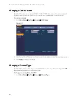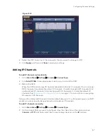
background image

Configuring Camera Settings 

61 

b.


Click 

Save

. The newly added camera appears in the 

Added


Device

 list. 

c.


Click 

Apply

 to save your settings. 

d.


If you want to save your settings and exit the 

Settings

 menu, click 

OK

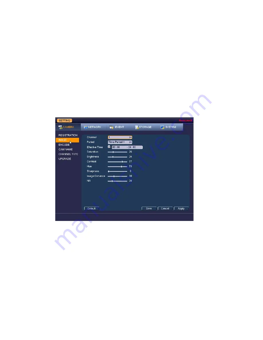
Configuring Image Settings 

You can configure the image settings (saturation, brightness, contrast, sharpness) for each 

connected camera. 
To configure a camera’s image settings 
1.


Go to 

Main Menu


Setting


Camera


Image

Figure 8-2 


2.


In the Channel box, select the camera that you want to configure. 

3.


In the Period, box, select a time period for the image settings. These image settings will be 

used only during this period. 

4.


In the Effective Time box, click to enter the start and end times for the Period you selected. 

5.


Configure the image saturation, brightness, contrast, and sharpness by moving the slider 

to the desired value. 


Saturation 

Select a value between 

and 

100

. The default setting is 

50


Brightness 

Select a value between 

0

 and 

100

. The default setting is 

50


Contrast 

Select a value between 

0

 and 

100

. The default setting is 

50


Hue 

Select a value between 

0

 and 

100

. The default setting is 

50


Sharpness 

Select a value between 

0

 and 

15

. The default setting is 

1


Image Enhance   

Select a value between 

0

 and 

100

. The default setting is 

30

Summary of Contents for HRHT4041

Page 1: ... Performance Series HQA Digital Video Recorder DVR Models HRHT4040 HRHT4080 HRHT4160 HRHT4041 HRHT4082 HRHT4162 HRHT4042 HRHT4084 HRHT4164 HRHT4166 HRHT41612 Local User Guide ...

Page 2: ...Issue Date Revisions A 04 2018 New document ...

Page 3: ...to provide reasonable protection against harmful interference in a residential installation This equipment generates uses and can radiate radio frequency energy and if not installed and used in accordance with the instructions may cause harmful interference to radio communications However there is no guarantee that interference will not occur in a particular installation If this equipment does cau...

Page 4: ...f the EMC directive 2014 30 EU conforming to the requirements of standards EN 55032 for emissions EN 50130 4 for immunity and EN 60950 1 for electrical equipment safety This is a Class B product Ina domestic environment this product may cause radio interference in which case the user may be required to take adequate measures Waste Electrical and Electronic Equipment WEEE Correct Disposal of this P...

Page 5: ...r as they may result in the risk of fire electric shock or injury to persons 8 ACCESSORIES Only use accessories specified by the manufacturer 9 CLEANING Do not use liquid cleaners or aerosol cleaners Use a damp cloth for cleaning 10 SERVICING Do not attempt to service this unit yourself as opening or removing covers may expose you to dangerous voltage or other hazards Refer all servicing to qualif...

Page 6: ......

Page 7: ...the Startup Wizard 20 3 Viewing Live Video 25 About Live View 25 Camera Status 26 Camera Toolbar 26 Configuring Live View 29 Setting the Screen Layout 29 Setting the Monitor Picture 29 Controlling PTZ Cameras 30 Configuring PTZ Connection Settings 31 Working with the PTZ Control Panel 32 Configuring PTZ Functions 34 Calling Presets Tours and Patterns 36 Configuring Auxiliary Settings 37 4 Recordin...

Page 8: ...UPnP Settings 80 Configuring SNMP Settings 81 Configuring Multicast Settings 82 Configuring P2P Settings 83 10 Configuring Event Settings 85 Configuring Motion Detection Settings 85 Configuring Video Loss Settings 89 Configuring Tampering Settings 90 Configuring Diagnosis Settings 91 Configuring Face Detection Settings 93 Configuring Alarms 95 Configuring Remote Alarms 95 Configuring Abnormality S...

Page 9: ...ring Users 129 Configuring Groups 131 Configuring Security 133 Configuring Automatic Maintenance Settings 134 Exporting and Importing System Configurations 135 Restoring Default Settings 137 Upgrading the DVR 137 13 Viewing Information 139 Viewing System Information 139 Viewing HDD Information 139 Viewing Recording Information 140 Estimating Recording Time and Space 141 Viewing Data Stream Informa...

Page 10: ...BS IP Hybrid DVR 8 channel DVRs HRHT4082 4 MP 8 channel 2 HDD Bay 2 TB HQA CVBS IP Hybrid DVR HRHT4084 4 MP 8 channel 2 HDD Bay 4 TB HQA CVBS IP Hybrid DVR 8 channel DVRs HRHT4082 4 MP 8 channel 2 HDD Bay 2 TB HQA CVBS IP Hybrid DVR HRHT4084 4 MP 8 channel 2 HDD Bay 4 TB HQA CVBS IP Hybrid DVR 16 channel DVRs HRHT4162 4 MP 16 channel 2 HDD Bay 2 TB HQA CVBS IP Hybrid DVR HRHT4164 4 MP 16 channel 2...

Page 11: ...channel typesettings Chapter 9 Configuring Network Settings describes how to configure the DVR s network settings including connection settings email settings FTP settings registration settings and alarm centersettings Chapter 10 Configuring Event Settings describes how to configure the DVR s alarm settings including settings for motion detection video loss camera tampering and system events Chapt...

Page 12: ...QA DVRs Remote User Guide Performance Series HQA DVRs Quick Installation Guide Performance Series HQA DVRs Quick Networking Guide To access a PDF version of these documents visit the Performance Series HQA DVR product page at www honeywellvideo com products video systems recording devices index html ...

Page 13: ...Panel Layouts 4 channel DVR Front Panel Figure 1 1 Table 1 1 Name Function 1 HDD Indicator Lights red when an HDD error occurs or when the HDD capacity is below the configured threshold 2 NET Indicator Lights red when a network error occurs or when there is no network connection 3 POWER Indicator Lights blue when the DVR receives power 4 USB 2 0 Port Connects USB devices USB flash drive mouse 1 2 ...

Page 14: ... Switch for turning DVR On Off 5 Ground Ground terminal 6 HDMI port HDMI interface for transmitting high definition audio and video output 7 Network port RJ45 100M Ethernet interface for connecting to local area network LAN 8 RS485 port RS485 interface for connecting RS485 devices PTZ cameras 9 USB 2 0 port USB 2 0 interface for connecting to USB device mouse USB flash drive portable HDD 10 Power ...

Page 15: ...liveview mode DisplaystheAssistant functionorconfiguresthe image color Text mode Deletes the last entered character when pressed and held for 1 5 seconds HDD management Switches HDD recording information 7 Record button Live view mode Starts stops recording 8 Play Previous button 0 Playback mode Plays the previous video Text mode Enters the number 0 9 Play Next button 9 Playback mode Plays the nex...

Page 16: ...r the number 5 or the letter J K or L 14 ESC Live view mode Returns to the previous menu or cancels the current operation Playback mode Returns to Live View mode 15 Directions keys 1 2 3 4 Menu setup Navigate up and down increase or decrease numbers PTZ mode Call up the assistant function for the PTZ menu Text mode Enter the numbers 1 2 3 or 4 or the letters A B C D E F G H and I 16 Enter Menu set...

Page 17: ...4 RS485 RS485 interface for connecting RS485 devices PTZ cameras 5 VGA port VGA connector for analog video output 6 Power switch Switch for turning DVR On Off 7 Ground Ground terminal 8 HDMI port HDMI interface for transmitting high definition audio and video output 9 USB 2 0 port USB 2 0 interface for connecting to USB device mouse USB flash drive portable HDD 10 Power input 12 V DC power input 1...

Page 18: ...the text box Table 1 5 Button Action 1 Left Click to select a menu option Click in text field to display on screen keyboard Click on screen keyboard to input letters numbers In multi screen view double click to view the channel full screen Double click again to exit full screen mode Double click video filename to play video 2 Right Click to close menu window without saving changes Click to exit ma...

Page 19: ...er number special character that you want to input in the text box To switch between the lowercase and uppercase letters click Shift To delete the previous character click the key To insert a space click the key 3 Click Enter to close the on screen keyboard ...

Page 20: ...w mode enter video search mode 8 Reverse Pause Pause resume reverse playback 9 Esc Return to previous menu or cancel current operation 10 Rec Manually start stop recording Whileinrecordinginterface usedirectionbuttonsto select recordingchannel Pressandholdrecordbutton toenter manual recording interface 11 Direction Keys Use left right keys to switch currently activated control Whileinplaybackmode ...

Page 21: ...cable s Serial ATA SATA cable s 1for 4 channel x2 for8 16 channel If any of the items listed above are missing or damaged contact your Honeywell dealer immediately Connecting External Devices Step 1 Connect the cameras Connect the coaxial cables from the cameras to the VIDEO IN connectors 1 Vp p 75 ohm Step 2 Connect the monitor Connect a VGA cable not supplied to the VGA interface and or an HDMI ...

Page 22: ...ilohm Step 6 Connect a PTZ camera if applicable To communicate with a PTZ camera connect it to the RS485 A and B input It is recommended to use shielded twisted pair cable with the shielded layer used to connect to the ground The ground should be the same as for the DVR and the voltage between the A and B lines should be less than 5 V Step 7 Connect the power cable Connect the supplied 12 V DC pow...

Page 23: ...Getting Started 11 Typical DVR Installation The following diagram shows a typical DVR installation Figure 2 1 ...

Page 24: ...eboot 4 Enter the admin password the default password is 1234 and then click OK Booting Up the DVR WARNING The rated input voltage matches the device power on off button Please make sure the power wire connection is OK Then click the power on off button To protect device please connect device to the power adapter first and then connect the power cable Always use the stable current if necessary UPS...

Page 25: ...confirm password The password ranges from 8 to 32 digitals It can contain letters numbers and special characters excluding The password shall contain at least two categories Usually we recommend the strong password Prompt question If you set the prompt question here On the login interface click device can display the corresponding prompt question for you to remind the password WARNING STRONG PASSW...

Page 26: ...re 2 4 Note The unlock pattern shall at least contain 4 grids Device adopts unlock pattern to login by default if you have set pattern here If there is no unlock pattern please input the password to login Click Skip if there is no need to set unlock pattern Figure 2 4 5 Input Email Address Email Input an email address for reset password purpose In case you forgot password in ...

Page 27: ...o skip this step 7 Click Save to complete the device initialization setup Reset Password If you forgot admin login password there are two ways for you to reset password When password reset function is enabled scan the QR code on the user interface and use the email to reset password When the password reset function is disabled answer the security questions to reset password If you have not set sec...

Page 28: ...lick If you have not input email address information when you are initializing the device the interface is shown as in Figure 2 7 Please input an email address and then click Next devices goes to Figure 2 8 If you have input email when you are initializing the device device goes to Figure 2 8 ...

Page 29: ...stions local menu only Email In Figure 2 8 follow the prompts on the interface to scan the QR code and then input the security code you get via the assigned email WARNING For the same QR code max scan twice to get two security codes Refresh the QR code if you want to get security code again The security code on your email is only valid for 24 hours ...

Page 30: ...urity question interface See Figure 2 9 Please input the correct answers here Note There is no security question item from the dropdown list if you have not set the security question and corresponding answers when initializing the device Figure 2 9 4 Click Next Device displays reset password interface See Figure 2 10 Figure 2 10 5 Input new password and then confirm ...

Page 31: ... and symbols We also recommend you change your password periodically especially in the high security system 6 Click Save to complete the reset setup Note A dialogue box pops up asking you to synchronize the password to the camera connecting by the default protocol Click OK to change the camera password The following window pops up if there is a digital channel Figure 2 11 Reset the Password Synchr...

Page 32: ...ideo standard Set the date and time Configure network settings Link your Honeywell smartphone app to the DVR Configure video encoding settings Set up a recording schedule Configure recording settings Note If you want to bypass the wizard and go directly to live view click Cancel To prevent Startup Wizard from opening the next time you start the DVR de select the Startup checkbox Using the Startup ...

Page 33: ...General window Figure 2 15 For more information about configuring settings in the General window see Configuring System Settings on page 115 3 Click Next to go to the Network window Figure 2 16 For more information about configuring settings in the Network window see Configuring TCP IP and Port Settings on page 71 ...

Page 34: ...P window Figure 2 17 For more information about P2P see Configuring P2P Settings on page 83 5 Click Next to go to the Encode window Figure 2 18 For more information about configuring settings in the Encode window see Configuring Encoding Settings on page 62 6 Click Next to go to the BASIC window ...

Page 35: ...2 19 7 Click Next to go to the Schedule window Figure 2 20 For more information about configuring settings in the Schedule window see Configuring the Video Recording Schedule on page 39 8 Click Next The Thank You message appears ...

Page 36: ...Performance Series HQA Digital Video Recorder Local User Guide 24 Figure 2 21 9 Click OK to close the wizard ...

Page 37: ...e View page 29 Controlling PTZ Cameras page 30 About Live View Live view is the DVR s default mode When you start the DVR live video from the connected cameras is displayed on the screen in a multi channel layout the number of channels displayed depends on whether you are using a 4 channel 8 channel or 16 channel DVR Figure 3 1 ...

Page 38: ...ignal Motion detected in scene Cameralocked Camera Toolbar A camera toolbaris locatedat thetop of each channelwindow To displaythetoolbar move the mouse pointer to the top of the channelwindow Figure 3 3 Table 3 1 INSTANT PLAY Play back the previous 5 to 60 minutes of recorded video Note The playback time is set to 5 minutes by default You can change this setting in Main Menu Setting System Genera...

Page 39: ...lickthebuttonto mute sound Click again to enablesound Note Mute only works in single channel view Live View Toolbar Figure 3 4 If enabled the live view toolbar appears along the bottom of the live view screen The toolbar is disabled by default To enable it right click and go to Main Menu Setting System General General and select the Navigation check box and then click Apply Right click twice to re...

Page 40: ...age29 Search Opentheplaybackinterface SeePlaying Back Videoon page44 Event Open the Event information window Channel Info Open the Channel Info window Camera Registration Click to register or add an IP camera See Registering Finding an IP Camera on page59 Network Open theNetworkwindow SeeConfiguring TCP IP and PortSettingson page71 HDD Manager Open theHDD Managewindow SeeConfiguring HDD Settingson...

Page 41: ...out button on the live view toolbar To change the screen display format using the mouse Rotate the mouse wheel button To move a channel to a different location in the multi channel grid Drag the channel to a new location in the multi channel grid For example to move channel 2 to the top left position occupied by channel 1 click channel 2 drag it to channel 1 s position then release the mouse butto...

Page 42: ...Customized and define the following settings Sharpness 0 15 Hue 0 100 Brightness 0 100 Contrast 0 100 Saturation 0 100 5 To configure settings for the remaining time in the Period box select Time Period 2 input the Effective Time and select a Color Mode or adjust the settings manually 6 Click OK to save your settings Controlling PTZ Cameras ThissectiondescribeshowtoconfigurePTZconnectionsettings h...

Page 43: ...ings Channel Select the channel camera that you want to configure PTZ settings for Control Mode Select HQA Protocol Select the camera s PTZ control protocol from the list Address Enter the camera s address ID Baudrate Select a value between 1200 and 115200 The default setting is 9600 Data Bits Select a value between 5 and 8 The default setting is 8 Stop Bits Select 1 1 5 or 2 The default setting i...

Page 44: ... click PTZ to pen the PTZ Control Panel Figure 3 8 Table 3 3 Name Function 1 Direction keys Direct camera movement 2 Speed Adjust the camera speed Select a value between 1 and 8 3 Expand Arrow Expand the control panel to display additional options 4 PTZ Trace Directcameramovementbydraggingthemouse Zoomin andout by rotating the wheelbutton 5 Zoom Focus Iris Adjust the camera s zoom focus and iris s...

Page 45: ... camera to continually pan between two points that you have defined 6 AutoPan Cause camera to continually rotate 360 degrees 7 Flip Cause camera to rotate 180 degrees 8 Reset Restore default settings 9 Aux Config Configure auxiliary functions To display the PTZ control panel 1 Right click anywhere on the screen to display the shortcut menu 2 Click Pan Tilt Zoom The PTZ control panel opens Figure 3...

Page 46: ...tton Figure 3 11 2 Use the direction arrows to point the camera where you want to set as the preset and then click Set Figure 3 12 3 In the Preset box enter a number for the preset and then click Set to save your settings To program additional presets repeat steps 1 through 3 To delete a preset enter the number of the preset that you want to delete in the Preset box and then click Del Preset Note ...

Page 47: ...t to delete in the Preset box and then click Del Preset To delete a tour enter the number of the tour that you want to delete in the Patrol No box and then click Del Tour Note Some protocols do not support the Del Preset function Configuring PTZ Patterns You can record a series of PTZ movements as a pattern When you call the pattern in live view mode the PTZ camera automatically moves along the pa...

Page 48: ...e PTZ camera s pan movement To program a scan 1 On the expanded PTZ control panel click the AutoScan button Figure 3 17 2 Use the direction arrows to set the camera s leftmost limit then click Left Figure 3 18 3 Use the direction arrows to set the camera rightmost limit then click Right Calling Presets Tours and Patterns To call a preset 1 On the expanded PTZ control panel in the No box enter the ...

Page 49: ... Tour button Figure 3 20 2 Click the Tour button again to stop calling the tour To call a pattern 1 On the expanded PTZ control panel in the No box enter the number of the pattern that you want to call and then click the Pattern button Figure 3 21 2 Click the Pattern button again to stop calling the pattern Configuring Auxiliary Settings Refer to the user guide of your PTZ camera for details on co...

Page 50: ...ckupbutton to start recording The button changes to green while the DVR is recording 5 Click the Realtime Backup button again to stop recording The video clip is saved automatically to the connected USB storage device The file name uses the following format DVR name _ channel _ video stream _ recording start time _ recording end time dav Automatic Record Settings The DVR supports independent real ...

Page 51: ...d page select the record types Auto Manual Stop that you want to enable on each channel for both the main stream and sub stream 3 Under Snapshot enable snapshot recording on the desired channels 4 Click Apply and then click OK Configuring the Video Recording Schedule To configure the video recording schedule 1 Go to Main Menu Setting Storage Schedule Record ...

Page 52: ...on detection recording schedule is indicated by a yellow bar Alarm The alarm recording schedule is indicated by a red bar MD Alarm The motion detection and alarm schedule is indicated by a blue bar Intel Intelligent identification recording or Face Detection recording is indicated by an orangebar 6 At the left of the scheduling table select the day s of the week that you want to configure a record...

Page 53: ... the Channel box select the channel camera that you want to configure a snapshot schedule for 3 At the top of the scheduling table select the check box es of the recording type s that you want to schedule Regular The regular recording schedule is indicated by a green bar MD The motion detection recording schedule is indicated by a yellow bar Alarm The alarm recording schedule is indicated by a red...

Page 54: ...click OK To configure snapshot recording settings 1 Go to Main Menu Setting Camera Encode Snapshot Figure 4 4 2 On the Snapshot tab configure the following settings Manual Snap Select the number of snapshots to take at a time Channel Select the channel that you want to configure the settings for Mode Select Timing to take snapshots according to a schedule Select Trigger to take snapshots when a mo...

Page 55: ...shots a higher priority than schedule activated snapshots If you have enabled both of these types of snapshots then the system activates an activation snapshot when an alarm occurs If there is no alarm then the DVR takes snapshots according to the schedule setup ...

Page 56: ...nu Operation Search The playback interface opens Figure 5 1 2 On the right panel of the playback interface in the calendar area click the date s that you want to search Dates with recorded video are solid orange 3 Below the calendar select the screen layout that you want to use and then select the channel s that you want to search 4 At the bottom of the screen select the recording type s that you ...

Page 57: ... Playback modes include slow play fast play reverse play and frame by frame playback 8 To jump forward or backward in the video click the time bar at the desired time To zoom in or out on the time bar click one of the options in the lower right corner of the screen 24 h 12 h 1 h or 30 min Smart Search To quickly locate activity using Smart Search 1 During video playback click the Smart Search butt...

Page 58: ...ea that you want to search for activity Figure 5 4 3 Click the Smart Search button again Playback jumps to all the parts of the video where there is activity in that area Figure 5 5 4 To exit Smart Search click the Smart Search button again The message Are you sure to exit smart search now appears Click OK ...

Page 59: ...arked Video 1 Click the Mark File List button while in Playback mode The Mark File list appears 2 Double click a marked file to begin playback Note If the marked file you want to play is missing the DVR begins playback from the first file in thelist Playing Back Before Marked Time In the Play back time before the mark field in the Playback interface you set the DVR to play N seconds of recorded vi...

Page 60: ...ted channel Note After opening the Marks Manager interface the DVR pauses current playback The DVR continues playback after you exit the Marks Manager interface Modifying Marked Video Note The only thing you can change about marked video is the name 1 Double click a marked time in the Marks Manager window A dialog box appears 2 Change the name of the marked time 3 Click OK Deleting Marked Video 1 ...

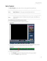
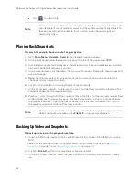
Page 61: ...differences might occur To simultaneously view multiple sections of a file 1 Click to enable Splice Playback in the Search window Figure 5 8 2 Select the Channel Date and the playback window layout the split mode The Splice Playback time bar uses a triangle to mark each section of the file Figure 5 9 3 Play back the recorded file Click Playback to play from the beginning of the current day by defa...

Page 62: ...ile List button to display the list of search results 7 In the list of search results double click the snapshot file that you want to play back The snapshot appears in the playback window 8 Playback cycles through all of the snapshot files in the file list at the interval you specified in the Interval box To pause playback click the Pause button in the control panel below the playback window To go...

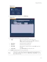
Page 63: ...vely during video playback in the video clip time field enter the desired start time and end time and then click the Backup button Figure 5 11 4 The Backup window opens displaying the selected video file clip 5 In the Backup window click Backup ...

Page 64: ...orage device opens Figure 5 13 6 Click Start to back up the file s If the backup is successful the message Backup finished appears To back up from outside of the playback interface 1 Insert a USB storage device such as a USB flash drive into one of the USB ports on the DVR The Find USB device dialog box opens ...

Page 65: ...uding snapshots Start Time Enter the start time of thesearch End Time Enter theend time of the search Record CH Select a specific channelto search or select All to search all channels File Format Select DAV or ASF as the videofileformat 4 Click Add to display the search results in the file list Note If there are too many files in the selected time only the first 1024 files in the search period wil...

Page 66: ...s HQA Digital Video Recorder Local User Guide 54 5 Select the check box es of the file s that you want to back up and then click Backup The Browse window of the USB storage device opens 6 Click OK to back up the file s ...

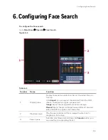
Page 67: ...op Click Export you can export the selected file to the USB device There are two types image record Image Export the recognized human face image Record Export the record file before and after 10 seconds when the DVR recognizes the human face 2 Playback pane Play the searched record file or image Double click to playback in full screen 3 Search pane Set date start time and end time click Search but...

Page 68: ...ackup device name and its total space and free space The device includes CD RW DVD burner USB device flash disk eSATA backup Figure 7 1 2 Select backup device and then set channel file format file start time and end time 3 Click Search the system begins to search All matched files will be listed as below The system automatically calculates the capacity needed and remained ...

Page 69: ...h a before channel name You can use Fn or cancel button to delete after file serial number 4 Click Backup system begins to copy the information At the same time the backup button becomes Stop button You can view the remaining time and process bar at the left bottom Figure 7 3 ...

Page 70: ... dav During backup process you can click ESC to exit current interface for other operation The system will not terminate backup process When you click stop button during the burning process the stop function becomes activated immediately For example if there are ten files when you click stop system just backup five files system only save the previous 5 files in the device But you can view ten file...

Page 71: ...3 Configuring Privacy Mask Settings page 64 Configuring the Text Overlay page 65 Changing a Camera Name page 66 Changing a Channel Type page 66 Upgrading Device page 70 Registering Finding an IP Camera Note You must first designate channels as IP rather than BNC or UTP apply that IP designation and reboot the DVR before you can see the REGISTRATION tab See Adding IP Channels on page67 To register ...

Page 72: ...d Device list OR Click Manual Add to manually add an IP camera a Manually configure the following settings Decode Buffer Select a decode buffer from Default Real Time or Fluent Channel Select from a drop down menu of options Manufacturer Select Private Panasonic Sony Dynacolor Samsung AXIS Arecont ONVIF PSIA or General IP Address Enter the IP address for the camera TCP Port Enter the TCP port for ...

Page 73: ...select a time period for the image settings These image settings will be used only during this period 4 In the Effective Time box click to enter the start and end times for the Period you selected 5 Configure the image saturation brightness contrast and sharpness by moving the slider to the desired value Saturation Select a value between 0 and 100 The default setting is 50 Brightness Select a valu...

Page 74: ...MD Motion Detection or Alarm The secondary stream type is not configurable Compression This setting is not configurable Smart Codec Select Start from the drop down menu to enable the Smart Codec function which reduces the video bit stream for non important recorded video to maximize storage space Resolution Set the primary stream to one of the following resolutions 2560 x 1440 1080P 720P 960H D1 H...

Page 75: ...urce Set to Local 4 Click Apply 5 To copy the settings to one or more additional cameras follow these steps a Click Copy b Click the specific camera s that you want to copy the settings to or click All to select all the cameras and then clickOK 6 Click Save to save your settings Note After you added IP camera to the DVR click Refresh after configuring Encode settings to ensure the Encode configura...

Page 76: ...Video Recorder Local User Guide 64 Figure 8 4 2 In the Channel box select the camera that you want to configure Configuring Privacy Mask Settings To configure a privacy mask 1 Go to Main Menu Setting Camera Encode Overlay Figure 8 5 ...

Page 77: ...ure 8 6 2 In the Channel box select the camera that you want to configure 3 To set the time display next to Time Display select the Record check box and then click Set Drag the time display to the desired position on the screen 4 To set the channel display next to Channel Display select the Record check box and then click Set Drag the channel display to the desired position on the screen 5 To copy...

Page 78: ...trance To rename a camera 1 Go to Main Menu Setting Camera CAM Name Figure 8 7 2 Click the text box of the camera that you want to rename and enter the new camera name 3 Click Apply to save your settings Changing a Channel Type By default the analog channel type is set to Coax You can change the channel type to UTP if unshielded twisted pair UTP cabling is used To change an analog channel to UTP 1...

Page 79: ...s 5 and 6 are the default IP channels On an 8 channel DVR channels 9 12 are the default IP channels On a 16 channel DVR channels 17 24 are the default IP channels See Registering Finding an IP Camera on page 59for instructions on assigning IP cameras to IP channels If you want toadd more IP channels than the defaultamount 2 4 or 8 depending on your DVR model you can manually designate analog chann...

Page 80: ... 4 2 1 2 4 6 5 4 3 1 1 5 6 5 4 3 2 0 6 6 5 4 3 2 1 8ch HQA DVR 8 1 2 3 4 5 6 7 8 4 12 11 10 9 7 1 2 3 4 5 6 7 5 12 11 10 9 8 6 1 2 3 4 5 6 6 12 11 10 9 8 7 5 1 2 3 4 5 7 12 11 10 9 8 7 6 4 1 2 3 4 8 12 11 10 9 8 7 6 5 3 1 2 3 9 12 11 10 9 8 7 6 5 4 2 1 2 10 12 11 10 9 8 7 6 5 4 3 1 1 11 12 11 10 9 8 7 6 5 4 3 2 0 12 12 11 10 9 8 7 6 5 4 3 2 1 16ch HQA DVR 16 1 2 3 4 5 6 7 8 9 10 11 12 1 3 14 8 24 ...

Page 81: ...6 24 23 22 21 20 19 18 17 16 1 5 14 13 12 11 10 9 7 1 2 3 4 5 6 7 17 24 23 22 21 20 19 18 17 16 1 5 14 13 12 11 10 9 8 6 1 2 3 4 5 6 18 24 23 22 21 20 19 18 17 16 1 5 14 13 12 11 10 9 8 7 5 1 2 3 4 5 19 24 23 22 21 20 19 18 17 16 1 5 14 13 12 11 10 9 8 7 6 4 1 2 3 4 20 24 23 22 21 20 19 18 17 16 1 5 14 13 12 11 10 9 8 7 6 5 3 1 2 3 21 24 23 22 21 20 19 18 17 16 1 5 14 13 12 11 10 9 8 7 6 5 4 2 1 2...

Page 82: ... Main Menu SETTING Camera UPGRADE Figure 8 10 Note you can distinguish the devices by Type Supported Camera Models Type COAXIAL HD30HD2 HD30XD2 HB74HD2 HE30XD2 HD274HD2 HE30XD2G HD231HD2 HB30XD2 HD31HD2 HD41XD2 HB276HD2 HB41XD2 HD74HD2 HE41XD2 HB76HD2 HC2HD2 HD274HD4 H4D42HD8 HB276HD4 HBD42HD8 HB74HD4 HFD40HD4 HD72HD4 HB30PHD2 HD30HD4 HB30THD2 ...

Page 83: ... Configuring PPPoE Settings page 76 Configuring DDNS Settings page 76 Configuring Sync Time page 78 Configuring Email Settings page 78 Configuring UPnP Settings page 80 Configuring SNMP Settings page 81 Configuring Multicast Settings page 82 Configuring P2P Settings page 83 Configuring Email Settings page 78 Configuring P2P Settings page 83 Configuring TCP IP and Port Settings To configure TCP IP ...

Page 84: ... If Mode is set to Static manually enter the IP Address Subnet Mask and Gateway information The IP address subnet mask and gateway are not configurable when Mode is set to DHCP 5 If Mode is set to Static and you have manually entered the IP Address Subnet Mask and Gateway then click Test to test the connection 6 If you want enter Preferred DNS and Alternate DNS addresses 7 Click Apply to save your...

Page 85: ...elect a value between 0 and 65535 The default setting is 80 HTTPS Port Select a value between 0 and 65535 The default setting is 443 RTSP Port Select a value between 0 and 65535 The default setting is 554 3 Click Apply to save your settings 4 If you want to exit the Setting menu click Save Note You must restart the DVR to apply any changes to the DVR s port settings Ensure that the port settings d...

Page 86: ...arch for Wi Fi hotspots clickRefresh To manually connect to a Wi Fi hotspot click Connection To disconnect from a Wi Fi hotspot click DisConnect If a Wi Fi connection is successfully established the Wi Fi hotspot name and connection details are displayed in the WIFI Working Information area 3 Click Apply to save your settings 4 If you want to exit the Setting menu click OK Note The system does not...

Page 87: ...less network AUTH Select the authentication mode that you want to use to access the wireless network PAP or CHAP Dial Number Enter the 3G 4G network dial up number that you received from your Internet service provider User Name Enter a user name for logging on to the 3G 4G network Password Enter a password for logging on to the 3G 4G network Dial Click Dial to manually enable or disable the 3G 4G ...

Page 88: ...e a PPPoE network connection 3 In the User Name and Password boxes enter the user name and password provided by your Internet service provider for PPPoE access 4 Click Apply and then click OK 5 Restart the DVR for the new network connection settings to take effect The DVR s new IP address appears on the PPPOE page Use this address when accessing the DVR remotely Configuring DDNS Settings To enable...

Page 89: ...omain to use the default domain name or click Custom Domain Name to create your own domain name Domain Name Enter a domain name if you are not using a default domain name You can obtain this from your DDNS service provider User Name If applicable enter a user name to access your DDNS service Password If applicable enter a password to access your DDNS service Email Address Unused Honeywell DDNS dom...

Page 90: ...face See Figure 9 7 3 Check the Enable box to enable Sync time function Figure 9 7 4 Click Apply or Save to complete setup Note If the DVR has enabled NTP service the device will sync time with the NTP server regularly The sync or change time operation of the IP address in the whitelist will be invalid unless the NTP server and the IP address in the whitelist is the same Configuring Email Settings...

Page 91: ...address where you want to send the notification You can enter up to three email addresses Sender Enter the sender s email address Subject Enter the email subject Attachment Select check box to enable sending an attachment with the email Encrypt Type Select an encryption type None SSL or TLS Interval This is the interval for sending emails Enter a time between 0 and 3600 seconds 0 means that there ...

Page 92: ... page configure the following settings PAT Click to Enable or Disable UPnP UPNP VAV Report Enable disable UPnP to work with I View Now LAN IP Enter the DVR s IP address from the TCP IP page WAN IP Enter the router IP address 3 Click Apply to save your settings Editing a Mapping Relationship If you want you can edit a mapping relationship from the PAT Table list 1 Click the mapping relationship tha...

Page 93: ... settings Version Select the check boxes of the SNMP version s that you are using SNMP Port The default setting is 161 Read Community The default setting is public Write Community The default setting is private Trap Address Enter the IP address of the computer running SNMP software Trap Port The default setting is 162 4 If SNMP Version V3 is selected the following settings are also configurable Re...

Page 94: ...gs Multicast allows for simultaneous real time monitoring of live video from the DVR at multiple remote locations over the network To configure multicast settings 1 Go to Main Menu Setting Network Multicast Figure 9 11 2 On the Multicast page select the Enable check box to enable multicast 3 In the IP Address box enter a multicast IP address The address must be valid for multicasting and should be...

Page 95: ...ess your DVR through the WAN To add a DVR to the Hon View Touch app 1 Go to Main Menu Setting Network P2P Figure 9 12 2 Open the app in your smartphone Note You can find the app in both the iOS App store and the Android Google Play store 3 Tap to go to Live Preview 4 Tap to open the Main Menu 5 Tap the Device Manager button then select P2P to add the device 6 Tap Start Live Preview to view video f...

Page 96: ...Performance Series HQA Digital Video Recorder Local User Guide 84 Figure 9 13 ...

Page 97: ... Settings page 93 Configuring Alarms page 95 Configuring Abnormality Settings page 97 Configuring Temperature and Humidity Camera IOT page 101 Configuring Motion Detection Settings To set up motion detection regions 1 Go to Main Menu Setting Event Video Detect Motion Detect Figure 10 1 2 On the Motion Detect tab in the Channel box select the channel camera that you want to configure motion detecti...

Page 98: ...tion region A grid appears over the live view screen and the following dialog box appears Figure 10 2 6 Set the Sensitivity level 0 100 and Threshold level 0 100 for Region1 Sensitivity refers to the amount of change as a percentage in the image pixels between frames Moving the Sensitivity slider to the left decreases the sensitivity of the motion detection and therefore more movement is required ...

Page 99: ... default when motion detection is enabled it is active all the time To modify the periods when motion detection for the selected channel is active on each day s timeline click the half hour blocks when you want motion detection to be disabled 3 Alternatively for the day of the week that you want to configure click Set The Period window opens Figure 10 4 ...

Page 100: ...in Menu Setting Event Video Detect Motion Detect Figure 10 5 2 On the Motion Detect tab select the actions that you want the system to initiate when a motion detection event occurs Anti Dither Configure the event detection lasting time anti dither During this time if another event is detected the DVR resets the recording time but does not reactivate the buzzer tour PTZ activation snapshot email Ch...

Page 101: ...urs and then click OK Delay Latch Set a length of time for the DVR to delay turning off events and activated input after an external alarm is cancelled Tour Select the check box to enable a tour of the selected channels Snapshot Select the check box to take a snaphot of selected channels Video Matrix Click to enable When an event occurs the SPOT OUT port video a 1 window tour from the event activa...

Page 102: ... detection is active next to Period click Set and then follow the steps listed in To set up motion detection periods on page 86 5 To set the actions that you want the system to initiate when a video loss event occurs follow the steps listed in To set up motion detection event actions on page 88 6 Click Apply to save your settings 7 To copy the settings to additional channels click Copy select the ...

Page 103: ...ext to Period click Set and then follow the steps listed in To set up motion detection periods on page 86 6 To set the actions that you want the system to initiate when a video tampering event occurs follow the steps listed in To set up motion detection event actions on page 88 7 Click Apply to save your settings 8 To copy the settings to additional channels click Copy select the channels that you...

Page 104: ... channel camera for which you want to configure diagnosis settings 4 Select the Enable check box to enable diagnosis for the selected channel 5 Click to configure the settings for the following parameters Stripe A vertical horizontal or diagonal stripe might occur due to electronic interference or age of the device Click to set the sensitivity ...

Page 105: ...lect the actions that you want the system to initiate when a diagnosis event occurs Show Message Select the check box to enable a pop up message on your local host PC Alarm Upload Select the check box to enable the system to upload an alarm signal to the network including to an alarm center and or web client Send Email Select the check box to enable the system to send an email notification If the ...

Page 106: ... you want to record In the Delay box specify the amount of time 1 300 s to delay recording after a motion detection event is triggered Note You also need to set the motion detection recording period Go to Storage Schedule to configure the current channel for scheduled recording See Configuring the Video Recording Schedule on page 39 PTZ Activation Select the check box to activate PTZ functions and...

Page 107: ...nfiguring Alarms If yourIPcamera hasalarm portsandalarm eventfunctions thentheDVRcan receivethealarm message from the camera and react by recording video taking a snapshot and or sending an email Configuring Remote Alarms ConfiguretheDVRtorecordvideo takea snapshot activatea PTZcamera preset tour pattern and or send an email if the DVR detects an issue with the I View Now software Click Remote Ala...

Page 108: ...ick the boxes besides the days to select the days to which to copy theperiods 3 Click Save Show Message Clicktoenablea pop up message on your local hostPCscreentolet you knowan alarm has occurred Send Email The systemcansendanemailwhen analarm is detected When you haveenabled theSnapshotfunction the system canalsosendanimage attachedtotheemail Go toMain Menu Setting Network Emailto configure theem...

Page 109: ...ce Snapshot Click to enable the Snapshot function Channel snapshots are taken according to the schedule you configure Alarm snapshots are taken when an alarm occurs Video Matrix Click to enable When an alarm occurs the SPOT OUT port video a 1 window tour from the alarm activation channel selected in the Record Channel Buzzer Click to enable the Buzzer function When an alarm occurs the buzzer beeps...

Page 110: ...hen the selected event occurs Show Message Select the check box to enable a pop up message on your local host PC Alarm Upload Select the check box to enable the system to upload an alarm signal to the network including to an alarm center and or web client Send Email Select the check box to enable the system to send an email notification Buzzer Select the check box to activate a buzzer noise at the...

Page 111: ... on your local host PC Send Email Select the check box to enable the system to send an email notification Record Channel Select the channel s that you want to record In the Delay box specify the amount of time 1 300 s to delay recording after a motion detection event is triggered Note You also need to set the motion detection recording period Go to Storage Schedule to configure the current channel...

Page 112: ... you want to configure settings for Illegal Login 3 Select the Enable check box to enable user error detection 4 Select the number of allowable Attempts before the action is taken from 0 to 255 5 Select how long the action lockout lasts from 0 to 60 minutes 6 Select the actions that you want the system to initiate when the selected event occurs Send Email Select the check box to enable the system ...

Page 113: ...his function please make sure there is at least one camera with temperature and humidity sensor has been connected to the Device Configuring Temperature To configure the temperature 1 Go to Main Menu Setting Event IOT Temperature Figure 10 15 2 On the Temperature tab select the Channel you want to configure and input the Alarm Name 3 Select the Enable check box to enable Temperature configuration ...

Page 114: ...ally starts recording selected channels when a motion detection alarm occurs Note You need to set the alarm recording period Go to Storage Schedule to configure the current channel for scheduled recording See Configuring Record Settings on page 111 PTZ Activation When PTZ activation is configured the system can activate 1 Click Set to open the PTZ Activationconfiguration interface 2 Selecta preset...

Page 115: ...oice Prompts Select to enable audio broadcast voice prompts in response to a motion detection event File Name Select a file for the voice prompt 5 Click Apply to save your settings Configuring Humidity To configure the Humidity 1 Go to Main Menu Setting Event IOT Humidity Figure 10 16 2 On the Humidity tab select the Channel you want to configure and input the Alarm Name 3 Select the Enable check ...

Page 116: ...en a motion detection alarm occurs Note You need to set the alarm recording period Go to Storage Schedule to configure the current channel for scheduled recording See Configuring Record Settings on page 111 PTZ Activation When PTZ activation is configured the system can activate 1 Click Set to open the PTZ Activationconfiguration interface 2 Selecta preset tour orpatternfromthedrop downmenu Click ...

Page 117: ...er Click to enable the Buzzer function When an alarm occurs the buzzer beeps Log Click to enable the DVR to record a local alarm log Voice Prompts Select to enable audio broadcast voice prompts in response to a motion detection event File Name Select a file for the voice prompt 5 Click Apply to save your settings ...

Page 118: ...Recording Schedule page 107 Configuring HDD Settings page 110 Configuring FTP page 111 Configuring Record Settings page 111 Configuring HDD Diagnostic Settings page 112 Configuring the Basic Settings Go to Main Menu SETTING STORAGE BASIC Figure 11 1 HDD Full Set to Overwrite to continue recording over old data when the HDD is full Set to Stop Record to stop recording when the HDD is full The defau...

Page 119: ...at you want to configure a recording schedule for 3 In the Pre Record box enter a time between 0 and 30 seconds The default setting is 4 seconds The pre record time sets how long the DVR records before the scheduled recording start time For example if the DVR is scheduled to start recording at 12 00 and the pre record time is set to 4 seconds the DVR will start recording at 11 59 56 4 If the DVR h...

Page 120: ...cording period click the eraser icon at the right of the table Alternatively for the day of the week that you want to configure click the gear icon at the right of the table In the Period window set up to six recording periods To copy the settings to additional days select the appropriate check box es under Copy and then click Save 8 Click Apply to save your settings 9 To copy the settings to addi...

Page 121: ...ndicated by an orange bar 4 At the left of the scheduling table select the day s of the week that you want to configure a recording schedule for To configure the same recording schedule for all of the days at the same time select All 5 Click or drag the mouse in the scheduling table to set the recording period To erase a recording period click the eraser icon at the right of the table Alternativel...

Page 122: ...amaged Device Name The HDD name Type The HDD type read write orread only Status The current operating status of theHDD Free Space Total Space The amount of free space remaining on the HDD The total capacity of the HDD 2 The HDD is configured as read write by default To change the HDD type to read only in the Type column select Read only HDD The DVR restarts to apply the new setting 3 To erase all ...

Page 123: ...d on to the FTP server Remote Directory Enter a name for the remote directory If this is left blank the NVR will automatically create folder names File Length This is the maximum size for image files being uploaded to the FTP server Enter a value between 0 and 65535 MB Image Upload Interval This is the interval for uploading images to the FTP server Enter a time between 1 and 600 seconds Channel S...

Page 124: ... Setting Storage Record Figure 11 6 2 On the Record page select the record types Schedule Manual Stop that you want to enable on each channel for both the main stream and secondary stream 3 Under Snapshot enable or disable snapshot recording on each channel 4 Click Apply to save your settings Configuring HDD Diagnostic Settings To run a diagnostic test on the HDD 1 Go to Main Menu Setting Storage ...

Page 125: ...want to run Quick Detect or Global Detect 3 In the HDD box select the check box of the HDD that you want to test 4 Click Start Detect to start the diagnostic test To view and or back up the diagnostic test results 1 Click the Report tab double click the report that you want to view The Details window opens Figure 11 8 ...

Page 126: ...are marked red 6 To back up the test results to an external USB storage device ensure that a USB storage device such as a USB flash drive in connected to one of the USB ports on the DVR and then click Backup to USB Devices If the backup is successful the message BackupSucceed appears 7 To view S M A R T Self Monitoring Analysis and Reporting Technology details click the S M A R T tab Figure 11 9 ...

Page 127: ... Zoom Settings page 124 Configuring ATM POS Card Overlay Settings page 125 Configuring Voice Settings page 127 Configuring Account Settings page 129 Configuring Security page 133 Configuring Automatic Maintenance Settings page 134 Exporting and Importing System Configurations page 135 Restoring Default Settings page 137 Upgrading the DVR page 137 Configuring General System Settings Configuring Dev...

Page 128: ...lt Auto Logout Set the length of time the DVR waits before logging out an inactive user Specify a time between 0 and 60 minutes The default setting is 10 min Navigation Bar Select the check box to display the live view toolbar on the live view screen Clear the check box to hide the live view toolbar IPC Time Sync input an interval here to synchronize the DVR time with the IPC time Startup Wizard S...

Page 129: ...rmat Select the time format that you want to use for the system time 24 Hour or 12 Hour Date Separator Select the separator that you want to use for the system time period hyphen or forward slash System Time Enter the system time and time zone and then click Save 3 Click Apply to save your settings To configure the Daylight Saving Time DST setting 1 Go to Main Menu Setting System General Date Time...

Page 130: ...Time tab select the NTP check box 4 In the Server IP box enter the IP address of the NTP server that you want to use for example time nist gov 5 Ensure that Port is set to 123 6 To change the frequency with which the system time synchronizes with the NTP server enter a new time in the Update Period box The default setting is 60 min 7 Click Manual Update to manually synchronize your system time wit...

Page 131: ...r more weeks as a holiday If Date is selected enter the year month and day in the Start Time and End Time boxes If Week is selected enter the year month week of the month 1st 2nd 3rd 4th Last and day 6 If you want to add more holidays select the Add More check box 7 Click Add to add the holiday 8 After you have added the new holidays on the Holiday Setup tab set the Status of each holiday Select E...

Page 132: ...e proportion Preview Enhancement To enhance the display image select the check box To keep the default settings clear the check box Transparency Set the transparency of the graphical user interface GUI to a value between 0 and 100 with 0 being totally opaque and 100 being totally transparent Resolution Set the resolution of your display Note You must restart the DVR for new display resolution sett...

Page 133: ...asinallof theavailableviews keepthedefaultsettings To create a custom tour for each view in the Window Split list View 1 View 4 clear the check box on thetop row of theChannel Group listto deselectallof the cameras for thatview thenselectthecamerasforeachviewthatyouwanttoappearinthetour Forexample tocreateatourshowingonlycameras2 3 and5insingle channelview set WindowSplittoView 1andthenselectcamer...

Page 134: ...nction or clear the check box to disable it Compression Select the desired video compression standard from the list The default setting is H 264 Resolution Select the desired video resolution from the list The default setting is D1 Frame Rate FPS Select a value between 1 and 30 NTSC or between 1 and 25 PAL Bit Rate Kb S Select a value between 896 and 4096 The default setting is 1024 3 Click Apply ...

Page 135: ...R waits before sending out email notifications after an event is detected Enter a time between 0 and 1440 minutes 0 means that there is no interval Resolution Select the desired video resolution from the list The default setting is D1 Window Split Select from the drop down list BNC supports only 1 split mode HDMI supports 1 4 9 16 split mode 3 Click Add to add a channel group 4 Click Apply to save...

Page 136: ...n Select Console Adapter or NetKeyboard depending on the type of RS232 device that you have connected to the DVR Baudrate Select a value between 1200 and 115200 The default setting is 115200 Data Bits Select a value between 5 and 8 The default setting is 8 Stop Bits Select 1 1 5 or 2 The default setting is 1 Parity Select None Odd Even Mark or Null The default setting is None 3 Click Apply to save...

Page 137: ...igure 12 10 2 On the Com tab configure the following settings Protocol Select None or POS Overlay Channel Select a camera Overlay Mode The Preview and Record overlay modes are enabled by default Clear the check boxes if you want to disable them Overlay Position Select Top Left Bottom Left Top Right or Bottom Right 3 Click Apply and then click Save to save the settings Configuring Net Settings You ...

Page 138: ... the recording Overlay Position Select Top Left Bottom Left Top Right or Bottom Right Source IP Port Enter the source IP and port The source IP refers to the host IP address that sends out the information Destination Port Enter the destination IP and port The destination IP refers to the IP address of the device that receives the information Record Channel Select a camera Frame ID Configure up to ...

Page 139: ...ault Clear the check boxes if you want to disable them Overlay Position Select Top Left Bottom Left Top Right or Bottom Right Source IP Port Enter the source IP and port The source IP refers to the host IP address that sends out the information Destination Port Enter the destination IP and port The destination IP refers to the IP address of the device that receives the information 3 Click Apply an...

Page 140: ... Manage Figure 12 13 2 Click Add to import an audio file from a USB device Note The audio file can either be saved to the HDD drive or remain on the USB device However the USB will have to remain connected to the DVR If the audio file is saved to the HDD then it is not necessary to have the USB device connected at all times 3 Click Apply and then click Save to save the settings Configuring the Voi...

Page 141: ...ick Apply and then click Save to save the settings Configuring Account Settings You can add edit or delete user accounts By default the DVR has an adminuseraccountand a defaultuseraccount Theadminuser accounthaspermission toperformalltheoperationand configurationfunctionsof theDVR Thedefaultuseraccount onlyhaspermissiontomonitor live video Configuring Users To add a user account 1 Go to Main Menu ...

Page 142: ...30 Figure 12 15 2 On the User tab click Add User The Add User page opens Figure 12 16 3 On the Add User page configure the following settings User Name Enter a user name for the account Password Enter a password for the account Confirm Password Re enter the password ...

Page 143: ...ettings To assign additional privileges change the user settings on the Group tab 4 Click Save to save your settings To edit a user account 1 Go to Main Menu Setting System Account User 2 On the User tab click the Modify icon of the user account that you want to edit The Modify User page opens 3 On the Modify User page you can change any of the following settings Password User Name User Group User...

Page 144: ...group 1 Go to Main Menu Setting System Account Group 2 On the Group tab click the Modify icon of the user group that you want to edit The Modify Group page opens 3 On the Modify Group page you can change any of the following settings Group Group Name Memo Authority System Playback Monitor 4 When you have finished making changes click Save to save your settings To delete a user group 1 Go to Main M...

Page 145: ...he trusted sites block sites Enable trusted site function and then add the whitelist Enable blocked site function and then add the blacklist 5 Set parameters Start address end address Select one type from the dropdown list you can input IP address in the start address and end address Now you can click Add IP address or Add IP section to add System supports max 64 IP addresses a For the newly added...

Page 146: ... Click it to edit start address and end address See Figure 12 19 System can check the IP address validity after the edit operation and implement IPv6 optimization Default Click it to restore default setup In this case the trusted sites and blocked sites are both null Figure 12 19 6 Click Apply or Save to complete setup If you enabled trusted sites only the IP in the trusted sites list can access t...

Page 147: ... your settings Exporting and Importing System Configurations You can export and or import DVR system configurations if you are installing several DVRs requiring the same setup To export a system configuration 1 Go to Main Menu Setting System IMP EXP 2 Insert a USB storage device such as a USB flash drive into one of the USB ports on the DVR The Find USB device dialog box opens Figure 12 21 3 In th...

Page 148: ...alog box opens 2 In the Find USB device dialog box click Config Backup 3 On the Config Backup page click the configuration file that you want to import named Config_ YYYYMMDDhhmmss and then click Import 4 Restart the DVR to apply the new settings To format an external USB storage device 1 Go to Main Menu Setting System Config Backup 2 Insert a USB storage device such as a USB flash drive into one ...

Page 149: ...rmat IP address and user accounts to be lost To restore default settings 1 Go to Main Menu Setting System Default Figure 12 23 2 Select the check boxes of the items that you want to restore to their default settings or select All to restore all of them to their default settings 3 Click Apply to save your settings Upgrading the DVR You can upgrade the system firmware locally at the DVR To upgrade t...

Page 150: ... USB flash drive containing the new firmware into one of the USB ports on the DVR The Find USB device dialog box opens Figure 12 25 3 In the Find USB device dialog box click System Upgrade 4 On the Upgrade page click Start The System Upgrade window opens 5 Select the firmware file from the file list and then click Start ...

Page 151: ...Event Information page 145 Viewing Network Information page 146 Viewing Log Information page 149 Viewing System Information InthesysteminformationinterfaceyoucanviewHDDinformation recordinformation bit stream statistics and versiondetails Viewing HDD Information To view HDD information 1 Go to Main Menu Info System HDD Info Figure 13 1 ...

Page 152: ...or example Read Write Total Space Indicates the total capacity of the HDD Free Space Indicates the amount of free space remaining on the HDD Status Indicates the operating status of the HDD S M A R T Indicates S M A R T Self Monitoring Analysis and Reporting Technology status 3 In the list of HDDs double click an HDD to view more details Figure 13 2 4 Right click to return to the previous screen V...

Page 153: ...d end times for recorded video Estimating Recording Time and Space You can calculate the recording time based on the available HDD space or you can calculate the HDD space you need for your recording time To estimate recording time 1 Go to Main Menu Info System REC ESTIMATE Figure 13 4 ...

Page 154: ...The Edit window appears Figure 13 5 3 Enter the Resolution Frame Rate Bit Stream and Recording Time of the channel 4 Click OK 5 Click Select under Known Space tab to select a HDD See the picture below Figure 13 6 The DVR calculates the recording time based on the channel setup and the HDD space ...

Page 155: ...ace 1 On the Rec Estimate tab click to select Known Time Figure 13 7 2 Enter how many days you want to record and the DVR estimates how much HDD is needed Viewing Data Stream Information To view data stream information Go to Main Menu Info System BPS ...

Page 156: ...rder Local User Guide 144 Figure 13 8 On the BPS page you can view the current video data stream rates and resolutions for each channel Viewing Channel Information To view channel information Go to Main Menu Info System ChannelInfo Figure 13 9 ...

Page 157: ...ng Version Information To view version information Go to Main Menu Info System Version Figure 13 10 On the Version page you can view the DVR model type record channel current hardware version system version build date web serial number and Onvif server version Viewing Event Information To view event information Go to Main Menu Info Event ...

Page 158: ...to date information Viewing Network Information In the network information interface you can view and or block online users view network data transmission details and perform network tests Viewing Online Users You can view the user name IP address and login time of all online users You can also block an online user for a specified period of time To view online users Go to Main Menu Info Network On...

Page 159: ...ation 147 Figure 13 12 Note Every five seconds the DVR system detects newly added or dropped users and updates the list of onlineusers To block an online user 1 Go to Main Menu Info Network Online Users Figure 13 13 ...

Page 160: ...You can enter up to 65535 seconds 18 2 hours Viewing Network Load Information To view network load information Go to Main Menu Info Network Load Figure 13 14 On the Load page you can view the network adapter name MAC address status Succeed or Failed device IP address network type the maximum transmission unit MTU send speed and receive speed Viewing Network Test Information To test the network 1 G...

Page 161: ...USB storage device 1 Insert a USB storage device such as a USB flash drive into one of the USB ports on the DVR 2 On the Test page under Network Sniffer Packet Backup click Refresh The connected USB storage device should appear in the Device Name box 3 If you want click Browse to set the savingpath 4 In the network devices list in the Sniffer Packet Backup column click the green arrow button to st...

Page 162: ...arch results are displayed in an ordered list The DVR can save up to 1024 log files 4 To view more details about a log entry click Details To back up log information to an external USB storage device 1 Insert a USB storage device such as a USB flash drive into one of the USB ports on the DVR The Find USB device dialog box opens Figure 13 17 2 In the Find USB device dialog box click Log Backup 3 On...

Page 163: ... and that the input voltage is correct and stable Make sure that the working environment is within the specified temperature range and is free of dust Remove the housing and check that the hard drive cables are firmly connected Problem The DVR cannot detect the hard drive Remove the housing and check that the hard drive cables are firmly connected Inspect the hard drive and ribbon for damage Repla...

Page 164: ...ions Check that the PTZ camera is connected correctly to the video input and RS485 port of the DVR Make sure that the DVR is configured correctly for PTZ operation The protocol and address settings of the DVR must match the protocol and address settings of the PTZ camera See Configuring PTZ Functions on page 34 Problem Motion detection does not work Increase the motion detection sensitivity It may...

Page 165: ...configured Check the alarm cable connections Check that you have not connected two loops to one alarm device Problem Cannot play a downloaded file Use the player included on the software CD Make sure that you have DirectX8 1 or greater installed on your computer If you are using Windows XP download the plug ins DivX503Bundle exe and ffdshow 20041012 exe ...

Page 166: ...kofelectricshock Disconnectpowerbefore removingcover To install an additional HDD 1 If the DVR is connected to a power source disconnect it before continuing 2 Remove the top cover from the DVR housing by removing the four screws securing it to the housing and then sliding the cover backwards 3 Connect the SATA and power cables to the new HDD 4 Position the new HDD over the four open screw holes i...

Page 167: ...e Seagate SV35 2 ST3500630SV 500 GB Seagate Seagate SV35 2 ST3750640SV 750 GB Seagate Seagate SV35 3 ST3250310SV 250 GB Seagate Seagate SV35 3 ST3500320SV 500 GB Seagate Seagate SV35 3 ST3750330SV 750 GB Seagate Seagate SV35 3 ST31000340SV 1 TB Seagate Seagate SV35 4 ST3320410SV 320 GB Seagate Seagate SV35 4 ST3250311SV 250 GB Seagate Seagate SV35 5 ST3500410SV 500 GB Seagate Seagate SV35 5 ST3500...

Page 168: ... 1 TB Seagate Seagate Pipeline HD2 ST1500VM002 1 TB Seagate Seagate Pipeline HD2 ST2000VM002 2 TB Seagate Seagate Pipeline HD2 ST2000VM003 2 TB Seagate Seagate Constellation ES ST3500514NS 500 GB Seagate Seagate Constellation ES ST31000524NS 1 TB Seagate Seagate Constellation ES ST32000644NS 2 TB Seagate Seagate Constellation ES ST2000NM0011 2 TB Seagate Seagate Constellation ES ST1000MN0011 1 TB ...

Page 169: ...tal WD AV AVJS WD3200AVJS 63WDA0 320 GB Western Digital WD AV AVJS WD5000AVJS 63YJA0 500 GB Western Digital WDAV GP AVCS WD5000AVCS 63H1B1 500 GB Western Digital WDAV GP AVCS WD7500AVCS 63ZLB0 750 GB Western Digital WDAV GP AVCS WD3200AVCS 320 GB Western Digital WDAV GP AVCS WD2500AVCS 250 GB Western Digital WDAV GP EVCS WD10EVCS 63ZLB0 1 TB Western Digital WDAV GP EVCS WD20EVCS 63ZLB0 2 TB Wester...

Page 170: ...amsung HD HD154UI CE 1 5 TB Hitachi HitachiCinemaStar 5K500 HCP725050GLA380 500 GB Hitachi HitachiCinemaStar 7K1000 BHCT721050SLA360 500 GB Hitachi HitachiCinemaStar 7K1000 BHCT721075SLA360 750 GB Hitachi HitachiCinemaStar 7K1000 BHCT721010SLA360 1 TB Maxtor DiamondMax 20 STM3320820AS 320 GB Maxtor DiamondMax 20 STM3250820AS 250 GB List of Compatible Portable HDDs Manufacturer Model Capacity YDSta...

Page 171: ...ored in the cloud for safe and secure backup The MAXPRO Cloud solution provides the following additional added value for customers and dealers Access on the go View live or recorded video anytime anywhere on your PC MAC laptop or mobiledevice Ease of remote management configuration and changes f w updates and increase managed services from a singlelogin Real time informative notifications with cli...

Page 172: ...A confirmation message appears Figure B 2 MAXPRO Cloud Configuration Confirmation Message 2 Click OK to confirm that you want to switch to MAXPRO Cloud mode The NVR restarts and opens in MAXPRO Cloud mode Note For information about operating in MAXPRO Cloud mode please Contact Honeywell CustomerService ...

Page 173: ......

Page 174: ...tschland Johannes Mauthe Straße 14 72458 Albstadt Germany www honeywell com security de 49 0 7431 801 0 Honeywell Security France Immeuble Lavoisier Parc de Haute Technologie 3 7 rue Georges Besse 92160 Antony France www honeywell com security fr 33 0 1 40 96 20 50 Honeywell Security Italia SpA Via della Resistenza 53 59 20090 Buccinasco Milan Italy www honeywell com security it 39 0 2 4888 051 Ho...

Reviews: