Maintenance
I nstall the camshaft and camshaft holders (page 8-8) .
Rotate the camshafts by rotating the crankshaft clockwise
several times.
Recheck the valve clearance .
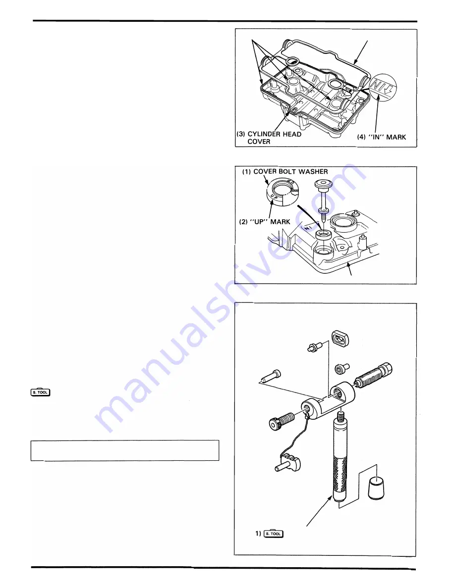
Apply Honda Bond A to the cylinder head cover g rooves as
shown.
Install the cover gasket with the "IN" mark facing the intake
side .
I nstall the cover bolt washer with the " U P" mark facing up.
Tighten the cover bolts .
Torque:
1 0
N·m
( 1 .0
kg-m,
7
ft-lbl
I nstall the removed parts in the reverse order of remova l .
Drive Chain
Replacement
The MAG NA VF7 50C uses a drive chain with a staked master
link.
Loosen the drive chain.
Assemble the special tool.
Drive chain cutter
NOTE
07HMH - M R 1 0 1 02
or
07HMH - MR 1 0 1 0B
(U.S.A.
only)
•
When using the special tool , follow the manufacture's
operating instructions.
3-8
(2) GROOVES
( 1 ) COVER GASKET
(3) CYLI N D E R H EAD COVE R
(
DRIVE CHAIN CUTTER
Summary of Contents for Magna VF750C
Page 1: ...1994 2003 MAGNA VF750C CD HONDA MOTOR CO LTD 1994 ...
Page 2: ......
Page 7: ...MEMO ...
Page 47: ...MEMO ...
Page 65: ...Fuel System Carburetor Removal Installation 5 4 ...
Page 67: ...Fuel System Carburetor Separation 1 5 26 5 6 ...
Page 69: ...Fuel System Carburetor DisassemblyIAssembly 23 1 2 1 5 1 4 0 ring gasket 5 8 ...
Page 71: ...Fuel System Carburetor Combination 27 D D No 1 CARBURETOR 25 0 RING COTIER PIN 5 5 1 0 ...
Page 81: ...Cooling System System Flow Pattern 1 SIPHON TUBE 5 THERMOSTAT 2 RESERVE TANK 3 WATE PUMP 6 2 ...
Page 87: ...MEMO ...
Page 109: ...MEMO ...
Page 113: ...Clutch System Clutch Removal 9 4 3 1 3 1 2 1 0 l a TooL I page 9 9 8 7 ...
Page 115: ...Clutch System Clutch Installation 1 0 0 9 6 ...
Page 121: ...Gearshift Linkage Gearshift Linkage Removal Installation 8 SHIFTER PLATE ASSEMBLY 1 1 0 4 ...
Page 123: ...MEMO ...
Page 125: ...Crankshaft Piston Transmission Crankcase Separation 6 5 1 1 2 ...
Page 131: ...Crankshaft Piston Transmission Transmission Removal Installation 1 1 1 8 ...
Page 143: ...MEMO ...
Page 145: ...Front Wheel Suspension Steering Handlebar Removal Installation 1 c2 3 2 3 1 7 1 1 0 1 5 1 2 2 ...
Page 189: ...MEMO ...
Page 223: ...MEMO ...
Page 227: ...MEMO ...
Page 243: ...Appendix A Part Numbers 23 10 Carburetor Assembly ...
Page 283: ...Appendix A Part Numbers 23 50 Speedometer Tachometer ...
Page 297: ...MEMO ...
Page 305: ... 1 ...


