•
Front cylinder (cont'd)
Turn the cam chain tensioner shaft com pletely in (clock
wise) and secu re it using the stopper tool .
This tool c a n easily b e made from a thi n ( 1 mm thick
ness) piece of steel.
15 m m 1 3.5 mm
3 mm
8.5 mm
1 5 m m
MATERIAL THICKNESS: 1 m m
3.5 m m
Insta l l a new gasket a n d cam chai n tensioner.
Torq ue the cam chai n tensioner mounting bolts.
Torque: 12 N·m ( 1 .2 kg-m, 9 ft-lb)
Remove the cam chain tensioner stopper tool .
Insta l l the c a m chain tensioner sea l i ng bolt a n d washer.
Make sure the timing marks on the camshaft sprockets
a re level with the cyl inder head u pper edge.
When The Rear Cylinder Camshaft Only Was Removed
A l i g n the " T2 " m a rk with the i ndex m a rk on the right
cra n kcase cover.
Remove the front cyli nder head cover ( page 8-2).
Make sure #2 cyli nder is TDC on the compression stroke.
If it is not, turn the cra n kshaft clockwise 360° a n d make
s u re "T2" m a rk a l igns with the i ndex mark o n the right
crankcase cover.
Rotate the cra n kshaft c lockwise 270° to a l ig n the "T1 "
m a rk with the i ndex mark on the right crankcase cover.
Head/Valves
( 1 ) TE NSIONER SHAFT
( 1 ) I N DEX MARK
(3) "T2" MARK
(2) TENSIONER STOPPER TOOL
(2) CAM CHAI N
TENSIONER
(2) RIGHT CRANKCASE COVER
8-1 3
Summary of Contents for Magna VF750C
Page 1: ...1994 2003 MAGNA VF750C CD HONDA MOTOR CO LTD 1994 ...
Page 2: ......
Page 7: ...MEMO ...
Page 47: ...MEMO ...
Page 65: ...Fuel System Carburetor Removal Installation 5 4 ...
Page 67: ...Fuel System Carburetor Separation 1 5 26 5 6 ...
Page 69: ...Fuel System Carburetor DisassemblyIAssembly 23 1 2 1 5 1 4 0 ring gasket 5 8 ...
Page 71: ...Fuel System Carburetor Combination 27 D D No 1 CARBURETOR 25 0 RING COTIER PIN 5 5 1 0 ...
Page 81: ...Cooling System System Flow Pattern 1 SIPHON TUBE 5 THERMOSTAT 2 RESERVE TANK 3 WATE PUMP 6 2 ...
Page 87: ...MEMO ...
Page 109: ...MEMO ...
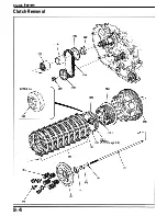
Page 113: ...Clutch System Clutch Removal 9 4 3 1 3 1 2 1 0 l a TooL I page 9 9 8 7 ...
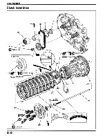
Page 115: ...Clutch System Clutch Installation 1 0 0 9 6 ...
Page 121: ...Gearshift Linkage Gearshift Linkage Removal Installation 8 SHIFTER PLATE ASSEMBLY 1 1 0 4 ...
Page 123: ...MEMO ...
Page 125: ...Crankshaft Piston Transmission Crankcase Separation 6 5 1 1 2 ...
Page 131: ...Crankshaft Piston Transmission Transmission Removal Installation 1 1 1 8 ...
Page 143: ...MEMO ...
Page 145: ...Front Wheel Suspension Steering Handlebar Removal Installation 1 c2 3 2 3 1 7 1 1 0 1 5 1 2 2 ...
Page 189: ...MEMO ...
Page 223: ...MEMO ...
Page 227: ...MEMO ...
Page 243: ...Appendix A Part Numbers 23 10 Carburetor Assembly ...
Page 283: ...Appendix A Part Numbers 23 50 Speedometer Tachometer ...
Page 297: ...MEMO ...
Page 305: ... 1 ...


