Gearshift
NOTE
•
Gearshift l i n kage service can be performed with the engine in the frame.
•
When removi ng the water pu m p, it is not necessary to d iscon nect the water hoses.
•
After insta llation, check the gearshift linkage for proper operation.
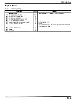
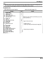
Requisite Service
•
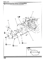
Drive sprocket cover removal/instal lation (page 1 0-2)
Procedure
O'ty
Removal Order
( 1 ) Gearsh ift linkage cover bolt/washer
5/2
(2) Gearshift linkage cover
1
(3)
Gasket/dowel pin
1/2
(4) Gear shift spindle assembly
1
(5) Washer
1
(6) S h ifter collar
1
(7) Shifter plate attach ing bolt
2
(8)
Sh ifter plate assembly
1
(9)
Shift drum center bolt
1
( 1 0) Shift drum center
1
( 1 1 ) Dowel pin
1
( 1 2) Washer
1
( 1 3) Stopper a rm spring
1
( 1 4) Stopper a rm assembly
1
( 1 5) Collar
1
( 1 6) Dowel pin
2
( 1 7 ) Shift d r u m bea ring stopper plate
1
•
Water pump removal/instal lation (page 6-7)
Remarks
I nsta llation is i n the reverse order of removal.
NOTE
•
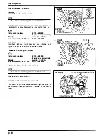
When rem ovin g and insta l l i ng, turn the l i n kage cover
slightly clockwise.
I n sta l l the sh ifter col l a r i nto the s p i n d l e hole, and the
return spring onto the return spring pin.
L u b ricate each pa rt with engine oil, a n d assem bly as
i l l ustrated. I nsta l l on the sh ift drum center with the drum
center positioned at any gea r stop except neutra l .
Apply a
agent to the threads.
I n sta l l by a l i g n i n g the cut out with the d owe l p i n as
shown .
I n sta l l the s n a p r i n g with t h e c h a mfe red s i d e fac i n g
i nside, a n d seat fu lly i n the flange collar g roove.
1 0-5
Summary of Contents for Magna VF750C
Page 1: ...1994 2003 MAGNA VF750C CD HONDA MOTOR CO LTD 1994 ...
Page 2: ......
Page 7: ...MEMO ...
Page 47: ...MEMO ...
Page 65: ...Fuel System Carburetor Removal Installation 5 4 ...
Page 67: ...Fuel System Carburetor Separation 1 5 26 5 6 ...
Page 69: ...Fuel System Carburetor DisassemblyIAssembly 23 1 2 1 5 1 4 0 ring gasket 5 8 ...
Page 71: ...Fuel System Carburetor Combination 27 D D No 1 CARBURETOR 25 0 RING COTIER PIN 5 5 1 0 ...
Page 81: ...Cooling System System Flow Pattern 1 SIPHON TUBE 5 THERMOSTAT 2 RESERVE TANK 3 WATE PUMP 6 2 ...
Page 87: ...MEMO ...
Page 109: ...MEMO ...
Page 113: ...Clutch System Clutch Removal 9 4 3 1 3 1 2 1 0 l a TooL I page 9 9 8 7 ...
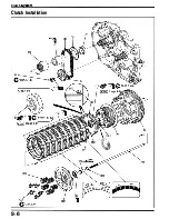
Page 115: ...Clutch System Clutch Installation 1 0 0 9 6 ...
Page 121: ...Gearshift Linkage Gearshift Linkage Removal Installation 8 SHIFTER PLATE ASSEMBLY 1 1 0 4 ...
Page 123: ...MEMO ...
Page 125: ...Crankshaft Piston Transmission Crankcase Separation 6 5 1 1 2 ...
Page 131: ...Crankshaft Piston Transmission Transmission Removal Installation 1 1 1 8 ...
Page 143: ...MEMO ...
Page 145: ...Front Wheel Suspension Steering Handlebar Removal Installation 1 c2 3 2 3 1 7 1 1 0 1 5 1 2 2 ...
Page 189: ...MEMO ...
Page 223: ...MEMO ...
Page 227: ...MEMO ...
Page 243: ...Appendix A Part Numbers 23 10 Carburetor Assembly ...
Page 283: ...Appendix A Part Numbers 23 50 Speedometer Tachometer ...
Page 297: ...MEMO ...
Page 305: ... 1 ...


