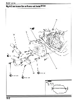
Head/Valves
NOTE
•
Service the front cyli nder head using the same proced u re as the rea r cyli nder.
•
Apply engine oil to the seat and threads of the cyli nder head bolts.
•
Before removi ng the engine mounting bolts from the cyl inder head, support the engine with a jack or other s u p
port to avoid over-loading the other bolts.
Requisite Service
Rear cylinder:
•
Ca mshaft remova l/insta l lation (page 8-2, 8)
•
Carbu retor removal/insta l lation ( page 5-4)
Front cylinder:
•
Camshaft remova l/instal lation (page 8-2, 8)
•
M uffler removal/i nsta l lation (page 2-4)
•
Air suction pipe remova l/i nsta l lation (Ca l ifornia type
on ly)
Procedure
Q'ty
Removal Order
( 1 ) Cylinder head 6 m m bolt
(2) Cylinder head 9 m m bolt/washer
(3) Cyl i nder head protector bolt
6
(4) Cyli nder head protector
2
(5) Cyli nder head
1
(6) Cylinder head gasket
1
(7) Dowel pin
2
•
Thermostat removal/instal lation ( page 6-4)
•
Air suction pipe remova l/instal lation (Ca l ifornia type
on ly)
•
Carbu retor remova l/insta l lation i page 5-4)
•
Thermostat removal/insta l lation (page 6-4)
Remarks
•
Loosen the fasteners in a criss-cross pattern i n 2 or 3
steps.
•
Refer to page 8- 1 7 for installation.
Disassem bly ( page 8-6)
Instal l with the
"
U P
"
mark facing up and " I N " m a rk fac-
ing i ntake side.
8-5
Summary of Contents for Magna VF750C
Page 1: ...1994 2003 MAGNA VF750C CD HONDA MOTOR CO LTD 1994 ...
Page 2: ......
Page 7: ...MEMO ...
Page 47: ...MEMO ...
Page 65: ...Fuel System Carburetor Removal Installation 5 4 ...
Page 67: ...Fuel System Carburetor Separation 1 5 26 5 6 ...
Page 69: ...Fuel System Carburetor DisassemblyIAssembly 23 1 2 1 5 1 4 0 ring gasket 5 8 ...
Page 71: ...Fuel System Carburetor Combination 27 D D No 1 CARBURETOR 25 0 RING COTIER PIN 5 5 1 0 ...
Page 81: ...Cooling System System Flow Pattern 1 SIPHON TUBE 5 THERMOSTAT 2 RESERVE TANK 3 WATE PUMP 6 2 ...
Page 87: ...MEMO ...
Page 109: ...MEMO ...
Page 113: ...Clutch System Clutch Removal 9 4 3 1 3 1 2 1 0 l a TooL I page 9 9 8 7 ...
Page 115: ...Clutch System Clutch Installation 1 0 0 9 6 ...
Page 121: ...Gearshift Linkage Gearshift Linkage Removal Installation 8 SHIFTER PLATE ASSEMBLY 1 1 0 4 ...
Page 123: ...MEMO ...
Page 125: ...Crankshaft Piston Transmission Crankcase Separation 6 5 1 1 2 ...
Page 131: ...Crankshaft Piston Transmission Transmission Removal Installation 1 1 1 8 ...
Page 143: ...MEMO ...
Page 145: ...Front Wheel Suspension Steering Handlebar Removal Installation 1 c2 3 2 3 1 7 1 1 0 1 5 1 2 2 ...
Page 189: ...MEMO ...
Page 223: ...MEMO ...
Page 227: ...MEMO ...
Page 243: ...Appendix A Part Numbers 23 10 Carburetor Assembly ...
Page 283: ...Appendix A Part Numbers 23 50 Speedometer Tachometer ...
Page 297: ...MEMO ...
Page 305: ... 1 ...


