Clutch
NOTE
•
When removing the oil pump d riven sprocket, loosen the sprocket bolt before removi ng the clutch assem bly. The
bolt is treated with a locking agent so be carefu l not to damage the bolt when loosen ing.
Requisite Service
•
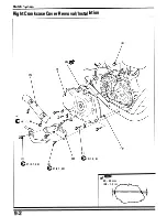
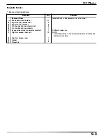
Right cra n kcase cover removal ( page 9-2)
Procedure
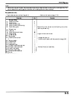
Removal Order
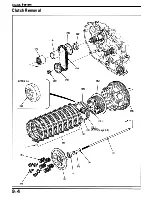
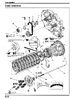
( 1 ) Clutch spring bolt
(2) Clutch spring
(3) Clutch pressure plate
(4)
Clutch pressure plate bearing
(5) Clutch lifter guide
(6) Stopper ring
(7) · Lifter rod
(8) Clutch disk A/cl utch plate
(9) Clutch disk
B
( 1 0) J udder spring
( 1 1 ) Spring seat
( 1 2) Clutch center lock n ut
{ 1 3) Spring washer
( 1 4) Clutch center
( 1 5) Clutch outer
( 1 6) N eedle bearing
( 1 7 ) O i l pum p driven sprocket bolt
( 1 8) Oil pump d riven sprocket
( 1 9) Clutch outer guide
(
2
0) Oil pum p d rive chain
(2 1 ) Oil pump d rive sprocket
(22)
Col l a r
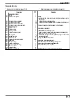
Q'ty
5
5
1
1
1
1
1
8/8
1
1
1
1
1
1
1
1
1
1
1
1
1
1
•
Starter cl utch removal (page 1 7- 1 0)
Remarks
Deta c h fro m t h e pres s u re p l ate b e a r i n g o n l y w h e n
replacing the bea ri ng.
Larger I . D. tha n clutch disc A
•
Unstake the lock n ut.
•
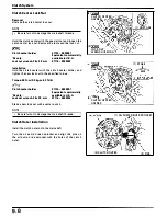
Hold the clutch center with the special tool ( page 9-8).
•
Remove them as a n assem bly.
9-5
Summary of Contents for Magna VF750C
Page 1: ...1994 2003 MAGNA VF750C CD HONDA MOTOR CO LTD 1994 ...
Page 2: ......
Page 7: ...MEMO ...
Page 47: ...MEMO ...
Page 65: ...Fuel System Carburetor Removal Installation 5 4 ...
Page 67: ...Fuel System Carburetor Separation 1 5 26 5 6 ...
Page 69: ...Fuel System Carburetor DisassemblyIAssembly 23 1 2 1 5 1 4 0 ring gasket 5 8 ...
Page 71: ...Fuel System Carburetor Combination 27 D D No 1 CARBURETOR 25 0 RING COTIER PIN 5 5 1 0 ...
Page 81: ...Cooling System System Flow Pattern 1 SIPHON TUBE 5 THERMOSTAT 2 RESERVE TANK 3 WATE PUMP 6 2 ...
Page 87: ...MEMO ...
Page 109: ...MEMO ...
Page 113: ...Clutch System Clutch Removal 9 4 3 1 3 1 2 1 0 l a TooL I page 9 9 8 7 ...
Page 115: ...Clutch System Clutch Installation 1 0 0 9 6 ...
Page 121: ...Gearshift Linkage Gearshift Linkage Removal Installation 8 SHIFTER PLATE ASSEMBLY 1 1 0 4 ...
Page 123: ...MEMO ...
Page 125: ...Crankshaft Piston Transmission Crankcase Separation 6 5 1 1 2 ...
Page 131: ...Crankshaft Piston Transmission Transmission Removal Installation 1 1 1 8 ...
Page 143: ...MEMO ...
Page 145: ...Front Wheel Suspension Steering Handlebar Removal Installation 1 c2 3 2 3 1 7 1 1 0 1 5 1 2 2 ...
Page 189: ...MEMO ...
Page 223: ...MEMO ...
Page 227: ...MEMO ...
Page 243: ...Appendix A Part Numbers 23 10 Carburetor Assembly ...
Page 283: ...Appendix A Part Numbers 23 50 Speedometer Tachometer ...
Page 297: ...MEMO ...
Page 305: ... 1 ...


