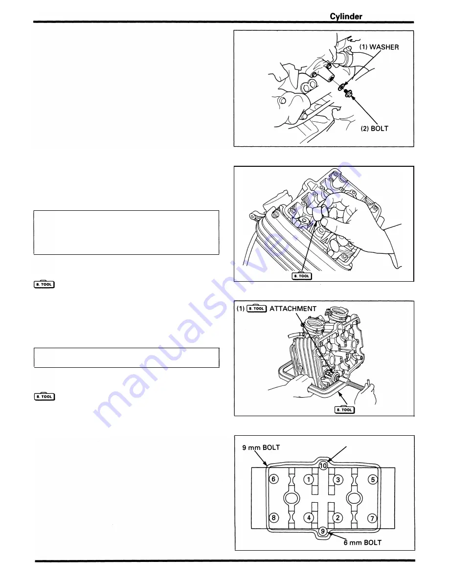
Remove the cam chain tensioner stopper tool .
Insta l l the cam chain tensioner sealing bolt and washer.
Make sure the ti ming ma rks on the camshaft sprockets are
level with the cyl inder head upper edge.
Valve Cotter Removal/Installation
Remove the va lve lifters and shi ms.
N OTE
•
M a rk the positions of a l l va lve l ifters and shims to
ensure correct reassem bly.
•
It is easy to remove the valve lifter with a valve lap
ping tool or magnet.
•
Remove the shims with tweezers or a magnet.
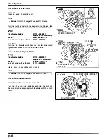
I nsta l l the ta ppet hole protector i nto the va lve lifter bore.
Tappet hole protector
07HMG - MR70002
Not available in U.S.A
I n sta l l the va lve spring com presso r onto the va lve a n d
compress the valve spring.
CAUTION:
•
To prevent loss of tension, do not compress the
valve springs more than necessary.
Remove the va lve cotters.
Valve spring compressor
07757 - 001 0000
Valve spring compressor attachment
07959 - KM30101
I nsta l lation is i n the reverse order of removal .
Cylinder Head Bolt Installation
Apply engine oil to the seating su rface and threads, then
tig hten the cyl i nder head m o u nting bolts g ra d u a l ly in a
crisscross pattern i n the order as shown .
Torque:
6 mm bolt: 12 N·m ( 1 .2 kg-m, 9 ft·lb)
9 mm bolt: 44 N·m (4.4 kg·m, 32 ft·lb)
Head/Valves
( 1 )
TAPPET HOLE PROTECTOR
(2)
COMPRESSOR
6
m m
BOLT
8- 1 7
Summary of Contents for Magna VF750C
Page 1: ...1994 2003 MAGNA VF750C CD HONDA MOTOR CO LTD 1994 ...
Page 2: ......
Page 7: ...MEMO ...
Page 47: ...MEMO ...
Page 65: ...Fuel System Carburetor Removal Installation 5 4 ...
Page 67: ...Fuel System Carburetor Separation 1 5 26 5 6 ...
Page 69: ...Fuel System Carburetor DisassemblyIAssembly 23 1 2 1 5 1 4 0 ring gasket 5 8 ...
Page 71: ...Fuel System Carburetor Combination 27 D D No 1 CARBURETOR 25 0 RING COTIER PIN 5 5 1 0 ...
Page 81: ...Cooling System System Flow Pattern 1 SIPHON TUBE 5 THERMOSTAT 2 RESERVE TANK 3 WATE PUMP 6 2 ...
Page 87: ...MEMO ...
Page 109: ...MEMO ...
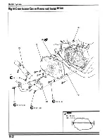
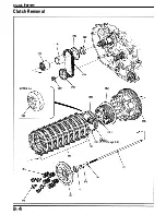
Page 113: ...Clutch System Clutch Removal 9 4 3 1 3 1 2 1 0 l a TooL I page 9 9 8 7 ...
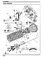
Page 115: ...Clutch System Clutch Installation 1 0 0 9 6 ...
Page 121: ...Gearshift Linkage Gearshift Linkage Removal Installation 8 SHIFTER PLATE ASSEMBLY 1 1 0 4 ...
Page 123: ...MEMO ...
Page 125: ...Crankshaft Piston Transmission Crankcase Separation 6 5 1 1 2 ...
Page 131: ...Crankshaft Piston Transmission Transmission Removal Installation 1 1 1 8 ...
Page 143: ...MEMO ...
Page 145: ...Front Wheel Suspension Steering Handlebar Removal Installation 1 c2 3 2 3 1 7 1 1 0 1 5 1 2 2 ...
Page 189: ...MEMO ...
Page 223: ...MEMO ...
Page 227: ...MEMO ...
Page 243: ...Appendix A Part Numbers 23 10 Carburetor Assembly ...
Page 283: ...Appendix A Part Numbers 23 50 Speedometer Tachometer ...
Page 297: ...MEMO ...
Page 305: ... 1 ...


