●
Input/output (I/O) specifications 4-10
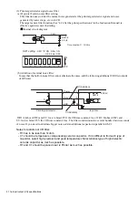
Print target detector
TB1
DC24V
Signal
NC
Power
Signal
GND
1
2
NC
4
3
・
SW1 "3": ON
・
SW1 "5": OFF
・
SW1 "6": OFF
ON
1
SW1 setting
ON
OFF
2
3
4
5
6
7
8
DC24V
GND
24VDC dedicated
power supply
Print target detector
Signal
Power
Signal
GND
・
SW1 "3": OFF
・
SW1 "5": OFF
・
SW1 "6": ON
SW1 setting
DC24V
GND
24VDC dedicated
power supply
TB1
GND
NC
1
2
NC
4
3
ON
1
ON
OFF
2
3
4
5
6
7
8
Tr
GND
DC24V
Power
Signal
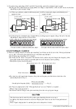
SW1-6
Print target detector
IJ printer
IL
1
2
3
(c) When NPN interface and dedicated power
supply are used
(d) When PNP interface and dedicated power
supply are used
Tr
GND
DC24V
DC24V
Signal
SW1-5
Print target detector
IJ printer
1
2
3
IL
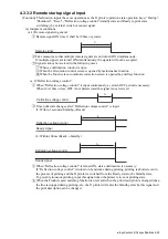
(2) Print target detector specifications
(a) When NPN interface is used
Internal circuit diagram
When the IJ printer input circuit is a current drive load for the print target detector output circuit and
output transistor Tr of the print target detector is ON, it becomes the print start signal input.
Use an output transistor Tr which satisfies the following specifications (NPN/PNP):
Withstand voltage
: 24VDC or greater
Maximum drive current : 12mA or greater (IL= 10mA)
Residual voltage
: 2V or less
Leakage current
: 0.1mA or less
The IJ printer built-in power supply specifications are:
Power supply voltage
: 24V
Maximum supply current
: 100mA *Note 1
*Note 1: Total power supply to print target detector and rotary encoder is max. 100mA
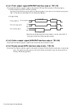
(b) When PNP interface is used
Internal circuit diagram
.
.

