4-11
●
Input/output (I/O) specifications
1kΩ
SW1-8
2.2μF
・
SW1 "8" ON : Filter ON
OFF: Filter OFF
ON
1
SW1 setting
ON
OFF
2
3
4
5
6
7
8
Time constant
t=
2.2ms
GND
1
2
3
C1(Addition)
R1(Addition)
Tr
DC24V
Power
Signal
SW1-5
Print target detector
IJ printer
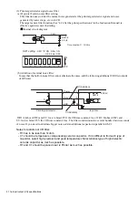
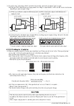
(3) Print target detector signal noise filter
(a) IJ printer built-in noise filter setting.
This function uses to filter the normal noise generated at the print target detector signal and noise
generated by water drops, etc. with CR.
The target sensor filter function (See “4.14 Set the print specifications” in the Instruction Manual) is
effective against sensor chattering.
Internal circuit diagram
(b) Addition of external noise filter
In case that the built-in noise filter cannot eliminate the noise, add the following additional CR filter outside
of IJ Printer.
If R1=1kohm (0.5W) and C1=1micro farad /25V, the CR time constant=1ms. If R1=1kohm (0.5W) and
C1=1micro farad /25V, the CR time constant=1ms. The filter could eliminate a several hundred micro-seconds
of noise. If you need to eliminate bigger noise, add an additional capacitor in parallel with C1.
Notes for addition of CR filter:
- R1 has to be less than 1kohm.
- C1 should be temperature compensating ceramic capacitor. If it is difficult to find such type of
capccitor, select high-precision and good temperature characteristics type of high dielectric
ceramic capacitor as much as possible.
- R1 and C1 should be placed near IJ Printer as much as possible.


