


Chapter 7 Explanation of Functions
7 - 22
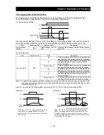
7.5.2 Torque boost setting
The torque boost setting function allows you to compensate for the voltage drop due to wiring and the
primary resistance of the motor so as to improve the motor torque at low speeds.
When you select automatic torque boost by the torque boost selection (A041/A241), adjust the settings of
the motor capacity selection (H003/H203) and motor pole selection (H004/H204) based on the motor to be
driven.
Item
Function code
Data or range of data
Description
Torque boost selection
A041/A241
00 Manual
torque
boost
01
Automatic torque boost
Manual torque boost value
A042/A242
0.0 to 20.0(%)
Setting of the rate of the boost to
the AVR voltage (A082/A282)
Manual torque boost frequency
adjustment
A043/A243
0.0 to 50.0(%)
Setting of the rate of the frequency
at breakpoint to the base frequency
(A003/A203)
Motor capacity
H003/H203
0.1 to 5.5(kW)
Selection of the motor capacity
Motor poles setting
H004/H204
2, 4, 6, 8 (poles)
Selection of the number of poles of
the motor
Voltage compensation gain
setting for automatic torque
boost
A046/A246
0. to 255.
See Item (2), "Automatic torque
boost."
Slippage compensation gain
setting for automatic torque
boost
A047/A247
0. to 255.
See Item (2), "Automatic torque
boost."
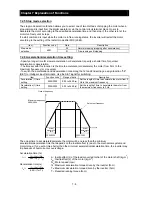
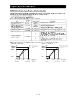
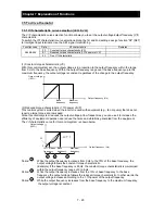
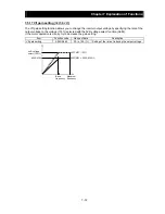
(1) Manual torque boost
The inverter outputs the voltage according to the settings of the manual torque boost (A042/A242) and
manual torque boost frequency adjustment (A043/A243).
Use the manual torque boost value (A042/A242) to specify the rate of the boost to the voltage (100%) set
by the AVR voltage select.
When increasing the value of the manual torque boost value, be careful to prevent motor over-excitation.
Over-excitation may result in motor burnout.
Use the manual torque boost frequency adjustment (A043/A243) to specify the rate of the frequency at
each breakpoint to the base frequency (100%).
To switch the settings among the 1st and 2nd settings ("A041 to A043" and "A241 to A243"), assign
function "08" (SET) to intelligent input terminals. Use the SET signal for switching.
Output voltage (%)
Base frequency
(100%)
Output
frequency
A042/A242
A043/A243
100
Summary of Contents for NES1-002LB
Page 9: ......
Page 21: ......
Page 25: ......
Page 28: ...Chapter 3 Exterior Views 3 3 ...
Page 30: ......
Page 35: ......
Page 53: ......
Page 75: ......
Page 154: ......
Page 196: ......
Page 203: ...Chapter 10 Troubleshooting This chapter describes the troubleshooting methods ...
Page 204: ......
Page 211: ......
Page 219: ......
Page 229: ......
Page 289: ...Appendix Appendix A Appendix A 1 ...
Page 290: ......
Page 292: ...Appendix Appendix 2 ...


