Chapter 13 Option
13 - 20
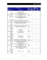
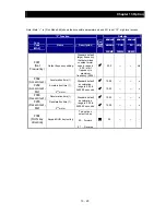
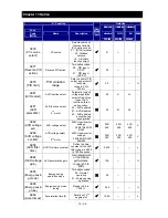
“C” Function
Run
Mode
Edit
Defaults
Func.
Code
Name
Description
Initial data
standard
200/400
Initial data
CHN
200/400
Initial data
EU
200/400
Units
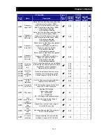
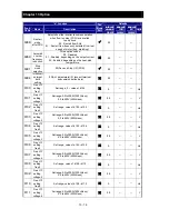
C241
Overload warning
level, 2
nd
motor
Rated
current
x 1.15
←
←
A
C042
Frequency arrival
setting for
acceleration
Sets the frequency arrival setting
threshold for the output frequency during
acceleration,
range is 0.00 to 400.00 Hz
0.00
←
←
Hz
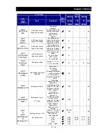
C043
Frequency arrival
setting for
deceleration
Sets the frequency arrival setting
threshold for the output frequency during
deceleration,
range is 0.00 to 400.00 Hz
0.00
←
←
Hz
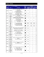
C044
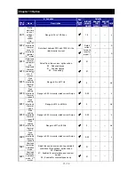
PID deviation level
Sets the allowable PID loop error
magnitude (absolute value), SP-PV,
range is 0.0 to 100%
3.0
←
←
%
C052
PID FBV output
high limit
When the PV exceeds this value, the
PID loop turns OFF the PID second
stage output, range is 0.0 to 100%
100.0
←
←
%
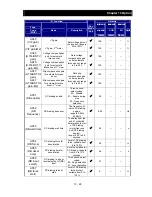
C053
PID FBV output
low limit
When the PV goes below this value, the
PID loop turns ON the PID second stage
output, range is 0.0 to 100%
0.0
←
←
%
C061
Electronic thermal
warning level
Set range is 0 to 100%
Setting 0 means disabled.
90
←
←
%
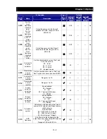
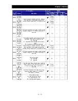
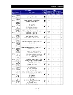
C063
Zero speed
detection level
Set range is 0.00 to 100.00Hz
0.00
←
←
Hz
C064
Heat sink overheat
warning
Set range is 0 to 110
C
100.
←
←
C
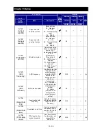
C070
Selection of
OPE/Modbus
00 (OPE) / 01 (Modbus)
00
←
←
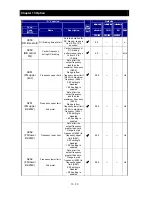
C071
Communication
speed
Five option codes:
04
4,800 bps
05
9,600 bps
06
19,200 bps
07
38,400 bps
05
←
←
bps
C072
Modbus address
Set the address of the inverter on the
network. Range is 1 to 247
1.
←
←
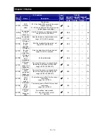
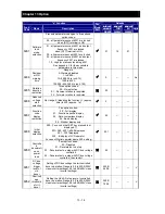
C074
Communication
parity
Three option codes:
00
No parity
01
Even parity
02
Odd parity
00
←
←
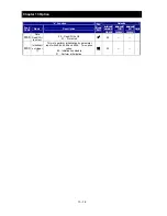
C075
Communication
stop bit
Two option codes:
01
1 bit
02
2 bit
01
←
←
C076
Communication
error select
Selects inverter response to
communications error.
Five options:
00
Trip
01
Decelerate to a stop and trip
02
Disable
03
Free run stop (coasting)
04
Decelerates to a stop
02
←
←
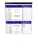
C077
Communication
error time-out
Sets the communications watchdog
timer period.
Range is 0.00 to 99.99 seconds.
0.0 = disabled
0.00
←
←
s
C078
Communication
wait time
Time the inverter waits after receiving a
message before it transmits.
Range is 0. to 1000. m seconds.
0.
←
←
ms
Summary of Contents for NES1-002LB
Page 9: ......
Page 21: ......
Page 25: ......
Page 28: ...Chapter 3 Exterior Views 3 3 ...
Page 30: ......
Page 35: ......
Page 53: ......
Page 75: ......
Page 154: ......
Page 196: ......
Page 203: ...Chapter 10 Troubleshooting This chapter describes the troubleshooting methods ...
Page 204: ......
Page 211: ......
Page 219: ......
Page 229: ......
Page 289: ...Appendix Appendix A Appendix A 1 ...
Page 290: ......
Page 292: ...Appendix Appendix 2 ...


