Chapter 7 Explanation of Functions
7 - 8
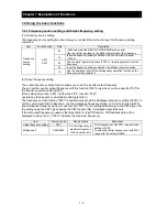
7.2.5 Stop mode selection
The stop mode selection function allows you to select one of two methods of stopping the motor when a
stop command is input from the digital operator or via the control circuit terminal block. One is to
decelerate the motor according to the specified deceleration time and then stop it; the other is to let the
motor run freely until it stops.
If a start command is input while the motor is in free-running status, the inverter will restart the motor
according to the setting of the restart mode after FRS (b088).
Item Function
code
Data
Description
Stop mode
selection
b091
00
Normal stopping (stopping after deceleration)
01
Free-running until stopping
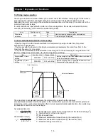
7.2.6 Acceleration/deceleration time setting
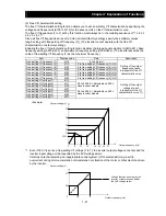
- Specify a longer time for slower acceleration or deceleration; specify a shorter time for quicker
acceleration or deceleration.
- The time set with this function is the time to accelerate (or decelerate) the motor from 0 Hz to the
maximum frequency (or vice versa).
- To switch the acceleration and deceleration time among the 1st and 2nd settings, assign function "08"
(SET) to intelligent input terminals . Use the SET signal for switching.
Item
Function code
Range of data
Description
Acceleration (1) time
setting
F002/F202
0.00 to 3600.(s)
Set the length of time to accelerate the motor from 0
Hz to the maximum frequency.
Deceleration (1) time
setting
F003/F203
0.00 to 3600.(s)
Set the length of time to decelerate the motor from
the maximum frequency to 0 Hz.
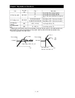
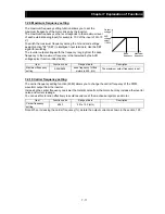
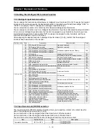
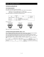
The actual time to accelerate/decelerate the motor will be no less than the minimum
acceleration/deceleration time that depends on the inertial effect (J) due to the mechanical system and
motor torque. If you set a time shorter than the minimum acceleration/deceleration time, the inverter may
trip because of overcurrent or overvoltage.
J
L
: Inertia effect (J) of the load converted to that of the motor shaft (kg-m
2
)
J
M
: Inertia effect (J) of the motor (kg-m
2
)
N
M
: Motor speed (rpm)
Ts: Maximum acceleration torque driven by the inverter (N-m)
T
B
: Maximum deceleration torque driven by the inverter (N-m)
T
L
: Required running torque (N-m)
Maximum frequency
A004/A204
F002/F202 F003/F203
Output frequency
Set output frequency
Actual
acceleration
time
Actual
deceleration
time
Acceleration time (ts)
Deceleration time (t
B
)
t
s
=
(J
L
+
J
M
)
×
N
M
9.55
×
(T
s
-
T
L
)
t
B
=
(J
L
+
J
M
)
×
N
M
9.55
×
(T
B
+T
L
)
Summary of Contents for NES1-002LB
Page 9: ......
Page 21: ......
Page 25: ......
Page 28: ...Chapter 3 Exterior Views 3 3 ...
Page 30: ......
Page 35: ......
Page 53: ......
Page 75: ......
Page 154: ......
Page 196: ......
Page 203: ...Chapter 10 Troubleshooting This chapter describes the troubleshooting methods ...
Page 204: ......
Page 211: ......
Page 219: ......
Page 229: ......
Page 289: ...Appendix Appendix A Appendix A 1 ...
Page 290: ......
Page 292: ...Appendix Appendix 2 ...


