Chapter 13 Option
13 - 21
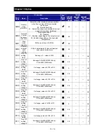
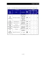
“C” Function
Run
Mode
Edit
Defaults
Func.
Code
Name
Description
Initial data
standard
200/400
Initial data
CHN
200/400
Initial data
EU
200/400
Units
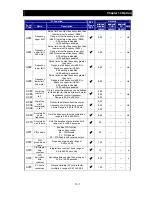
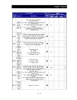
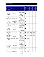
C081
O/OI input span
calibration
Scale factor between the external
frequency command on terminals L–O
/OI(voltage/current input) and the
frequency output,
range is 0.0 to 200%
100.0
←
←
%
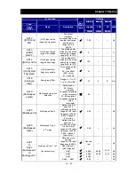
C091
Debug mode
enable *
Displays debug parameters.
Two option codes:
00
Disable
01
Enable
<Do not set>
(for factory use)
00
←
←
C101
Up/Down memory
mode selection
Controls speed setpoint for the inverter
after power cycle.
Two option codes:
00
Clear last frequency (return to
default frequency
)
01
Keep last frequency adjusted by
UP/DWN
00
←
←
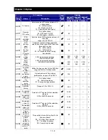
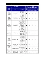
C102
Reset selection
Determines response to Reset input
[RS].
Three option codes:
00
Cancel trip state at input signal ON
transition, stops inverter if in Run
Mode
01
Cancel trip state at signal OFF
transition, stops inverter if in Run
Mode
02
Cancel trip state at input ON
transition, no effect if in Run Mode
00
←
←
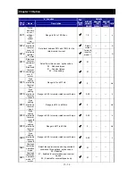
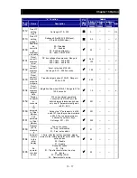
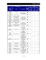
C103
Restart mode after
reset
Determines the restart mode after reset
is given, two option codes:
00
Start with 0 Hz
01
Start with freq. matching
00
←
←
C104
UP/DWN clear
mode
Freq. set value when UDC signal is
given to the input terminal, two option
codes:
00
0 Hz
01
Original setting (in the memory at
power on)
00
←
←
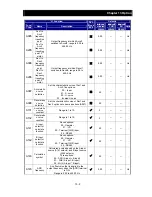
C105
FM gain
adjustment
Set range is 50 to 200%
100.
←
←
%
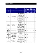
C130
Output [11] on
delay
Set range is 0.0 to 100.0 seconds.
0.0
←
←
s
C131
Output [11] off
delay
0.0
←
←
s
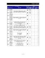
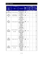
C140
Relay output on
delay
Set range is 0.0 to 100.0 seconds.
0.0
←
←
s
C141
Relay output off
delay
0.0
←
←
s
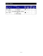
C142
Logic output 1
operand A
All the programmable functions available
for logic (discrete) outputs except LOG1 ,
no
00
←
←
C143
Logic output 1
operand B
00
←
←
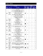
C144
Logic output 1
operator
Applies a logic function to calculate
[LOG] output state,
Three options:
00
[LOG] = A AND B
01
[LOG] = A OR B
02
[LOG] = A XOR B
00
←
←
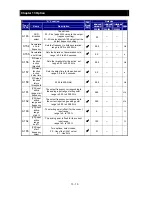
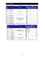
C151
Button sensitivity
selection
0 to 250 / no
10
←
←
Summary of Contents for NES1-002LB
Page 9: ......
Page 21: ......
Page 25: ......
Page 28: ...Chapter 3 Exterior Views 3 3 ...
Page 30: ......
Page 35: ......
Page 53: ......
Page 75: ......
Page 154: ......
Page 196: ......
Page 203: ...Chapter 10 Troubleshooting This chapter describes the troubleshooting methods ...
Page 204: ......
Page 211: ......
Page 219: ......
Page 229: ......
Page 289: ...Appendix Appendix A Appendix A 1 ...
Page 290: ......
Page 292: ...Appendix Appendix 2 ...

